ENGINE UNIT DISASSEMBLY

PROCEDURE
-
REMOVE SPARK PLUG
-
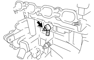
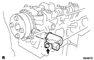
REMOVE KNOCK SENSOR
-
Remove the nut and the knock sensor.
-
-
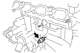
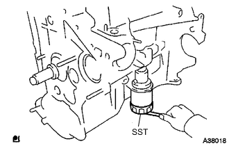
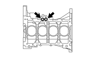
REMOVE ENGINE OIL PRESSURE SWITCH ASSEMBLY
-
Using a 24 mm (0.94 in.) deep socket wrench, remove the engine oil pressure switch assembly.
-
-
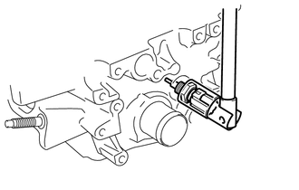
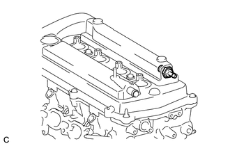
REMOVE ENGINE COOLANT TEMPERATURE SENSOR
-
Using a 19 mm (0.748 in.) deep socket wrench, remove the engine coolant temperature sensor.
-
-
REMOVE INLET WATER
-
REMOVE THERMOSTAT
-
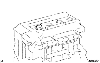
REMOVE OIL FILLER CAP SUB-ASSEMBLY
-
Remove the oil filler cap sub-assembly from the cylinder head cover sub-assembly.
-
-
REMOVE OIL FILLER CAP GASKET
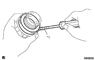
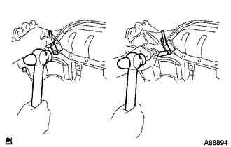
Text in Illustration *1 Protective Tape
-
Using a screwdriver with its tip wrapped in protective tape, remove the oil filler cap gasket from the oil filler cap sub-assembly.
-
-
REMOVE CRANKSHAFT POSITION SENSOR
-
Remove the bolt and the crankshaft position sensor.
-
-
REMOVE VENTILATION VALVE SUB-ASSEMBLY
-
Remove the ventilation valve sub-assembly from the cylinder head cover sub-assembly.
-
-
REMOVE CYLINDER HEAD COVER SUB-ASSEMBLY
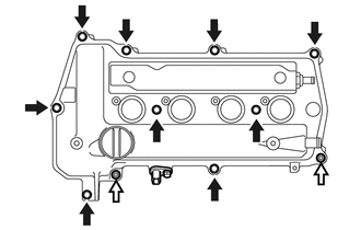
-
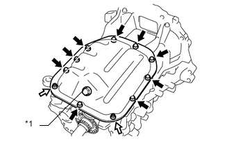
Remove the 9 bolts, 2 nuts and then remove the cylinder head cover sub-assembly.
Text in Illustration 
Bolt 
Nut
-
-
REMOVE CYLINDER HEAD COVER GASKET
-
Remove the cylinder head cover gasket from the cylinder head cover sub-assembly.
-
-
REMOVE CAMSHAFT TIMING OIL CONTROL VALVE ASSEMBLY
-
Remove the bolt and the camshaft timing oil control valve assembly.
-
-
REMOVE WATER PUMP PULLEY
-
REMOVE CRANKSHAFT DAMPER SUB-ASSEMBLY
-
REMOVE TRANSVERSE ENGINE ENGINE MOUNTING BRACKET
-
REMOVE ENGINE WATER PUMP ASSEMBLY
-
REMOVE OIL PUMP ASSEMBLY
-
REMOVE OIL PUMP SEAL
-
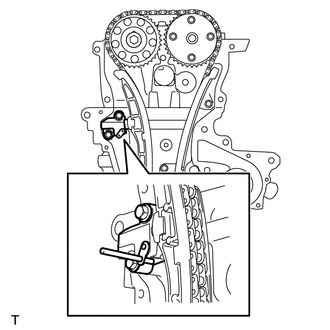
REMOVE NO. 1 CHAIN TENSIONER ASSEMBLY
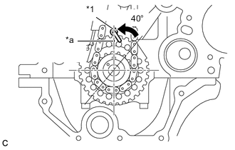
Text in Illustration *1 Oil jet *a Timing Mark Note
-
Do not rotate the crankshaft with the No. 1 chain tensioner assembly removed.
-
When rotating the camshaft with the chain sub-assembly removed, rotate the crankshaft counterclockwise 40° from TDC first, and align the oil jet hole with the paint mark. This prevents the pistons from coming into contact with the valves.
-
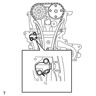
Text in Illustration *1 Stopper Plate Pull up the stopper plate and hold it with its lock released.
-
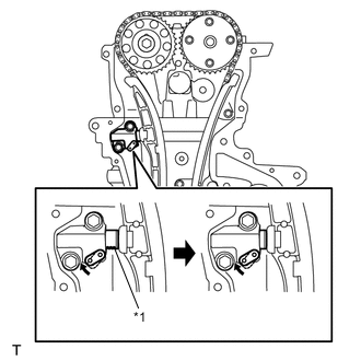
Text in Illustration *1 Plunger Unlock the plunger of the tensioner and push it in to the end.
-
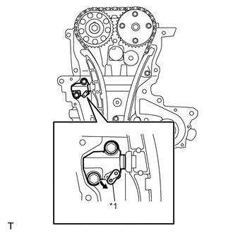
Text in Illustration *1 Stopper Plate Pull down the stopper plate with the plunger pushed to the end and lock the plunger.
-
Insert a 3.5 mm (0.14 in.) diameter bar into the hole in the stopper plate and lock the plunger.
-
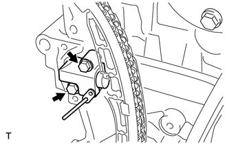
Remove the 2 bolts and the No. 1 chain tensioner assembly.
-
-
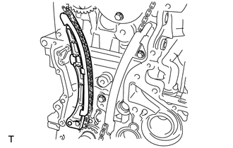
REMOVE CHAIN TENSIONER SLIPPER
-
Remove the chain tensioner slipper.
-
-
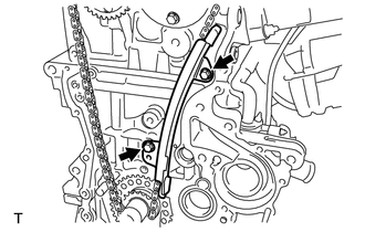
REMOVE NO. 1 CHAIN VIBRATION DAMPER
-
Remove the 2 bolts and the No. 1 chain vibration damper.
-
-
REMOVE CHAIN SUB-ASSEMBLY
-
Remove the chain sub-assembly.
-
-
REMOVE FUEL DELIVERY PIPE SUB-ASSEMBLY
-
REMOVE NO. 1 DELIVERY PIPE SPACER
-
REMOVE INJECTOR VIBRATION INSULATOR
-
REMOVE FUEL INJECTOR ASSEMBLY
-
REMOVE CAMSHAFT POSITION SENSOR
-
REMOVE NO. 2 CAMSHAFT
Note
Do not rotate the crankshaft with the No. 1 chain tensioner removed. When rotating the camshaft with the chain sub-assembly removed, rotate the crankshaft counterclockwise 40° from the TDC first, and align the oil jet hole with the paint mark. This prevents the pistons from coming into contact with the valves.
Text in Illustration *1 Oil jet *a Timing Mark (1 dot)
-
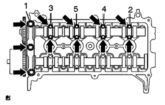
Using several steps, loosen and remove the 11 bearing cap bolts uniformly in the sequence shown in the illustration, then remove the No. 1 camshaft bearing cap, No. 2 camshaft bearing cap and No. 2 camshaft.
Note
Loosen each bolt uniformly while keeping the camshaft level.
-
-
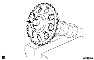
REMOVE CAMSHAFT TIMING SPROCKET
-
Clamp the No. 2 camshaft in a vise.
-
Remove the fringe bolt and the camshaft timing sprocket.
Note
Do not damage the No. 2 camshaft.
-
-
REMOVE CAMSHAFT
-
REMOVE CAMSHAFT TIMING GEAR ASSEMBLY
-
REMOVE NO. 1 VALVE ROCKER ARM SUB-ASSEMBLY
-
REMOVE VALVE LASH ADJUSTER ASSEMBLY
-
REMOVE VALVE STEM CAP
-
REMOVE CYLINDER HEAD SUB-ASSEMBLY
-
REMOVE CYLINDER HEAD GASKET
-
REMOVE OIL FILTER SUB-ASSEMBLY
-
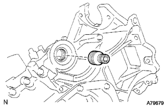
REMOVE OIL FILTER UNION
-
Using a 12 mm (0.47 in.) hexagon wrench, remove the oil filter union.
-
-
REMOVE REAR ENGINE OIL SEAL
-
REMOVE NO. 2 OIL PAN SUB-ASSEMBLY
-
Text in Illustration *1 Oil Pan Drain Plug Remove the oil pan drain plug and gasket.
-
Remove the 9 bolts and 2 nuts.
Text in Illustration Bolt Nut -
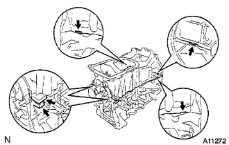
Insert the blade of oil pan seal cutter between the oil pan sub-assembly and No. 2 oil pan sub-assembly, and cut off the applied sealer and remove No. 2 oil pan sub-assembly.
Note
Do not damage the oil pan sub-assembly or No. 2 oil pan sub-assembly.
-
-
REMOVE OIL STRAINER SUB-ASSEMBLY
-
Remove the bolt and 2 nuts.
-
Remove the oil strainer and the gasket.
-
-
REMOVE OIL PAN SUB-ASSEMBLY
-
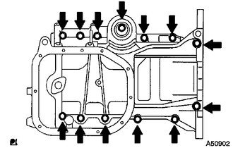
Loosen and remove the 13 bolts uniformly in several steps.
-
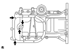
Using a screwdriver, remove the oil pan sub-assembly by prying between the cylinder block and oil pan sub-assembly.
Note
Do not damage the contact surfaces of the oil pan sub-assembly or the cylinder block.
-
Remove the 2 O-rings from the cylinder block.
-
-
REMOVE STUD BOLT
-
Remove the 4 stud bolts.
-