CYLINDER BLOCK REASSEMBLY

PROCEDURE
-
INSTALL OIL JET
-
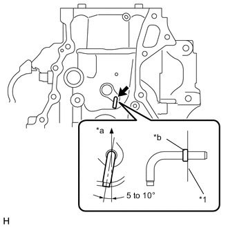
Text in Illustration *1 Cylinder block *a Upward *b Spool Install a new oil jet as shown in the illustration.
Note
Do not tap the tip of the oil jet.
Tech Tips
Press in the oil jet until the spool contacts the cylinder block.
-
-
INSTALL NO. 1 OIL NOZZLE SUB-ASSEMBLY
-
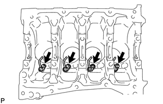
Using a 5 mm socket hexagon wrench, install the oil nozzles with the bolts.
- Torque:
- 10 N*m { 102 kgf*cm, 7 ft.*lbf }
-
-
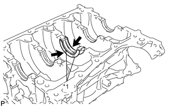
INSTALL OIL CHECK VALVE SUB-ASSEMBLY
-
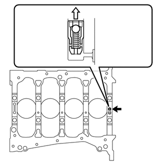
Install the oil check valve sub-assembly to the cylinder block.
Text in Illustration 
Crankshaft Bearing Side Note
-
Make sure that the oil check valve sub-assembly is not tilted.
-
Install the oil check valve sub-assembly before installing the crankshaft bearing.
-
When installing the crankshaft bearing, make sure it does not interfere with the oil check valve sub-assembly.
-
-
-
INSTALL PISTON
-
Gradually heat a new connecting rod to 80°C (176°F) or more.
-
Coat a new piston pin and pin holes in a new piston with engine oil.
-
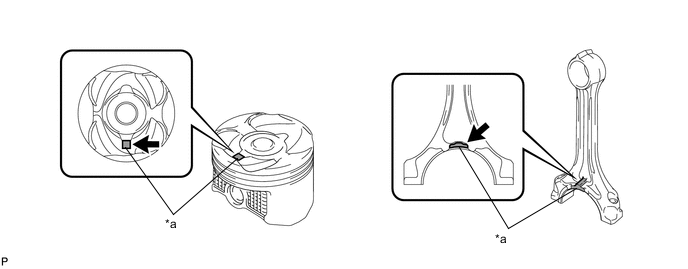
Align the front marks of the piston and connecting rod.
Text in Illustration *a Front Mark -
Using SST, press in the piston pin.
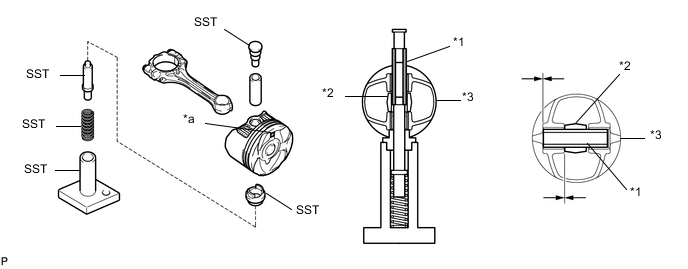
Text in Illustration *1 Piston Pin *2 Connecting Rod *3 Piston *a Front Mark - SST
- 09221-25026 ( 09221-00021, 09221-00030, 09221-00090, 09221-00100, 09221-00150 )
Note
-
Press in the piston pin from the side of the piston with the front mark shown in the illustration.
-
With the connecting rod fully inserted into the piston end, press in the piston pin until it is flush with the piston surface.
-
Check the fitting condition between the piston and piston pin by trying to move the piston back and forth on the piston pin.
-
-
INSTALL PISTON RING SET
-
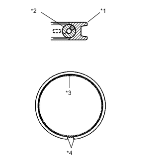
Text in Illustration *1 Oil Ring *2 Oil Ring Expander *3 Coil Joint *4 Oil Ring Ends Install the oil ring expander and oil ring by hand.
Note
-
Install the expander and oil ring so that their ring ends are at opposite sides.
-
Securely install the expander to the inner groove of the oil ring.
-
-
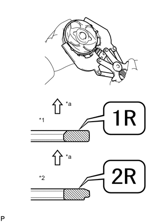
Text in Illustration *1 No. 1 Ring *2 No. 2 Ring *a Upward Using a piston ring expander, install the No. 1 ring and No. 2 ring as shown in the illustration.
Note
-
Install the No. 1 ring with the code mark (1R) facing upward.
-
Install the No. 2 ring with the code mark (2R) facing upward.
-
-
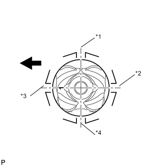
Text in Illustration *1 Oil Ring *2 No. 2 Ring *3 No. 1 Ring *4 Oil Ring Expander 
Engine Front Position the piston rings so that the ring ends are as shown in the illustration.
-
-
INSTALL CRANKSHAFT BEARING
-
Install the upper bearing.
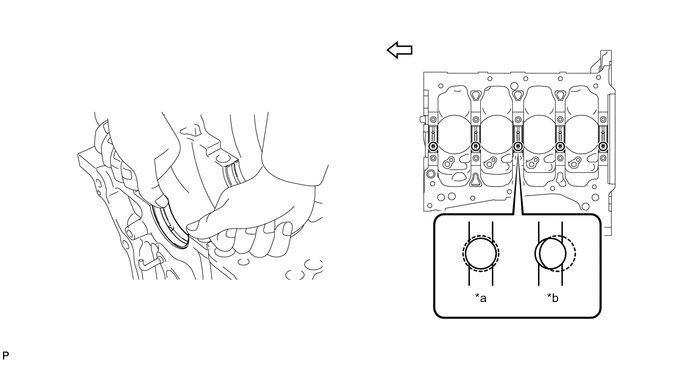
Text in Illustration *a Correct *b Incorrect Engine Front Note
-
Align the oil holes on the bearing and cylinder block.
-
Do not apply engine oil to the bearings or the contact surfaces.
-
-
Install the lower bearing.
-
Install the lower bearing onto the bearing cap.
-
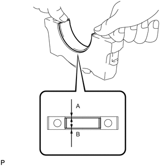
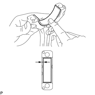
Using a vernier caliper, measure the distance between the bearing cap edge and the lower bearing edge.
Dimension (A - B) 0.7 mm (0.0276 in.) or less Note
Do not apply engine oil to the bearings or the contact surfaces.
-
-
-
INSTALL UPPER CRANKSHAFT THRUST WASHER
-
Text in Illustration *1 Oil Grooves Install the 2 thrust washers under the No. 3 journal of the cylinder block with the oil grooves facing outward.
-
Apply engine oil to the crankshaft thrust washers.
-
-
INSTALL CRANKSHAFT
-
Apply engine oil to the upper bearings and install the crankshaft on the cylinder block.
Text in Illustration *a Number Mark Engine Front -
Apply engine oil to the lower bearings.
-
Examine the number marks and install the bearing caps on the cylinder block.
-
Apply a light coat of engine oil to the threads and under the bearing cap bolts.
-
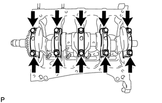
Temporarily install the 10 main bearing cap bolts.
-
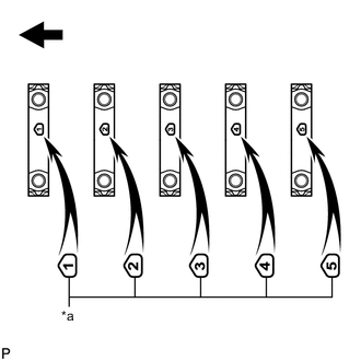
Step 1
-
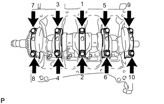
Install and uniformly tighten the 10 main bearing cap bolts in the sequence shown in the illustration.
- Torque:
- 30 N*m { 306 kgf*cm, 22 ft.*lbf }
-
-
Step 2
-
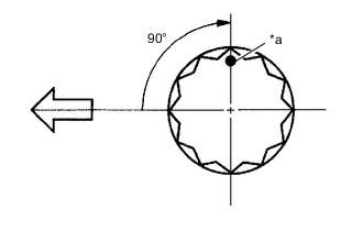
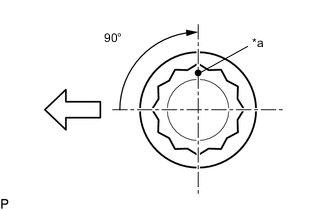
Text in Illustration *a Paint Mark Engine Front Mark the front of the bearing cap bolts with paint.
-
Further tighten the bearing cap bolts an additional 90° in the numerical order shown in the previous illustration.
-
-
Check that the paint mark is now at a 90° angle to the front.
-
Check that the crankshaft turns smoothly.
-
Check the crankshaft thrust clearance Click here.
-
-
INSTALL CONNECTING ROD BEARING
-
Install the connecting rod bearing to the connecting rod and bearing cap.
-
Using a vernier caliper, measure the distance between the connecting rod edge and connecting rod bearing edge.
Dimension 2.2 to 2.6 mm (0.0866 to 0.102 in.) Note
Do not apply engine oil to the bearings or the contact surfaces.
-
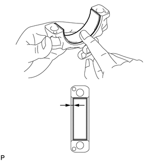
Using a vernier caliper, measure the distance between the bearing cap edge and connecting rod bearing edge.
Dimension 2.2 to 2.6 mm (0.0866 to 0.102 in.) Note
Do not apply engine oil to the bearings or the contact surfaces.
-
-
INSTALL PISTON SUB-ASSEMBLY WITH CONNECTING ROD
-
Apply engine oil to the cylinder walls, the pistons, and the surfaces of the connecting rod bearings.
-
Position the piston rings so that the ring ends are as shown in the illustration.
Text in Illustration *1 Oil Ring *2 No. 2 Ring *3 No. 1 Ring *4 Oil Ring Expander Engine Front Note
Do not align the ring ends.
-
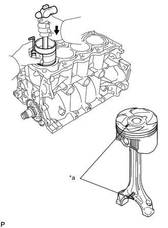
Text in Illustration *a Front Mark Using a piston ring compressor, push the correctly numbered piston and connecting rod assembly into the cylinder with the front mark of the piston facing forward.
Note
-
When inserting the piston with connecting rod, do not allow it to make contact with the oil nozzle.
-
Match the numbered connecting rod cap with the connecting rod.
-
-
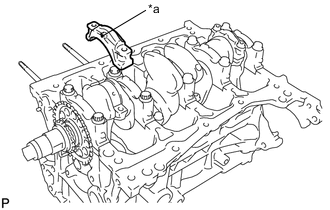
Text in Illustration *a Front Mark Check that the front mark of the connecting rod cap is facing in the correct direction.
-
Apply a light coat of engine oil to the threads and under the heads of the connecting rod cap bolts.
-
Install the connecting rod cap bolts.
Note
The connecting rod cap bolts should be tightened in 2 progressive steps.
-
Step 1
-
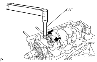
Using SST, install and alternately tighten the bolts of the connecting rod cap in several steps.
- SST
- 09205-16010
- Torque:
- 15 N*m { 153 kgf*cm, 11 ft.*lbf }
-
-
Step 2
-
Text in Illustration *a Paint Mark Engine Front Mark the front of the connecting rod cap bolts with paint.
-
Further tighten the cap bolts an additional 90° as shown in the illustration.
-
-
Check that the crankshaft turns smoothly.
-
Check the connecting rod thrust clearance Click here.
-