ENGINE UNIT INSPECTION

PROCEDURE
-
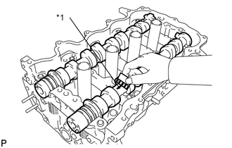
INSPECT CAMSHAFT TIMING GEAR ASSEMBLY
-
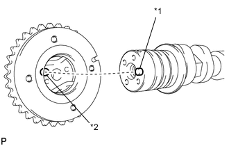
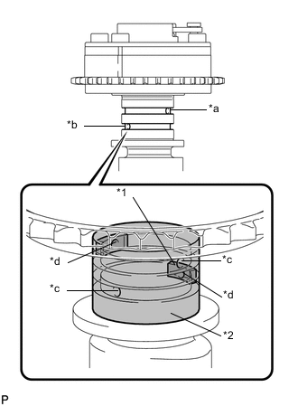
Text in Illustration *1 Straight Pin *2 Key Groove Install the camshaft timing gear.
-
Check that the knock pin is installed on the camshaft.
-
Put the camshaft timing gear and camshaft together by aligning the key groove and straight pin.
Note
-
Do not forcefully push in the camshaft timing gear assembly. This may cause the camshaft knock pin tip to damage the installation surface of the camshaft timing gear assembly.
-
Do not turn the camshaft timing gear in the retard direction (clockwise).
-
-
Tighten the flange bolt with the camshaft timing gear secured in place.
- Torque:
- 54 N*m { 551 kgf*cm, 40 ft.*lbf }
-
-
Check the lock of the camshaft timing gear.
-
Confirm that the camshaft timing gear is locked.
-
-
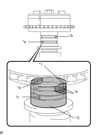
Text in Illustration *1 Rubber *2 Vinyl Tape *a Advance Side Path *b Retard Side Path *c Open *d Close Release the lock pin.
-
Cover the 4 oil paths of the cam journal with vinyl tape as shown in the illustration.
Tech Tips
There are 4 oil paths in the groove of the camshaft. Plug three of the paths with pieces of rubber.
-
Prick a hole in the tape placed on the retard side path, on the opposite side to that of the advance side path, as shown in the illustration.
-
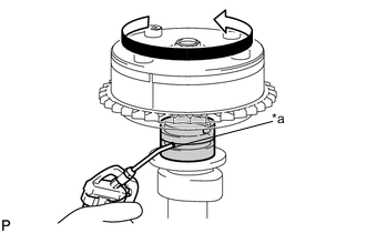
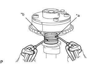
Text in Illustration *a Advance Side Path While applying approximately 150 kPa (1.5 kgf/cm2, 22 psi) of air pressure to the oil paths, forcibly turn the camshaft timing gear assembly in the advance direction (counterclockwise).
Note
-
Cover the paths with a piece of cloth when applying pressure to keep oil from splashing.
-
Do not lock the camshaft timing gear assembly. If it is locked, release the lock pin again.
Tech Tips
-
The camshaft timing gear assembly may be turned in the advance direction without applying any force.
-
If enough air pressure cannot be applied because of air leaks from the port, releasing the lock pin may be difficult.
-
-
-
Check for smooth rotation.
-
Turn the camshaft timing gear within its movable range (26.5 to 28.5°) 2 or 3 times, but do not turn it to the most retarded position. Make sure that the gear turns smoothly.
Note
Do not lock the camshaft timing gear assembly. If it is locked, release the lock pin again.
-
-
-
INSPECT CAMSHAFT TIMING EXHAUST GEAR ASSEMBLY
-
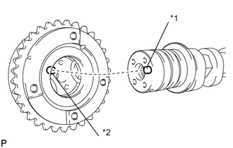
Text in Illustration *1 Straight Pin *2 Key Groove Install the camshaft timing exhaust gear.
-
Check that the knock pin is installed on the No. 2 camshaft.
-
Put the camshaft timing exhaust gear and No. 2 camshaft together by aligning the key groove and straight pin.
Note
-
Do not forcefully push in the camshaft timing gear assembly. This may cause the camshaft knock pin tip to damage the installation surface of the camshaft timing gear assembly.
-
Be sure not to turn the camshaft timing exhaust gear in the retard direction (clockwise).
-
-
Tighten the flange bolt with the camshaft timing exhaust gear secured in place.
- Torque:
- 54 N*m { 551 kgf*cm, 40 ft.*lbf }
-
-
Check the camshaft timing exhaust gear lock.
-
Make sure that the camshaft timing exhaust gear is locked.
-
-
Text in Illustration *1 Rubber *2 Vinyl Tape *a Advance Side Path *b Retard Side Path *c Open *d Close Release the lock pin.
-
Cover the 4 oil paths of the cam journal with vinyl tape as shown in the illustration.
Tech Tips
The 4 oil paths are provided in the grooves. Plug 2 paths with rubber pieces.
-
Prick a hole in the tape placed on the advance side path. Prick a hole in the tape placed on the retard side path, on the opposite side to that of the advance side path, as shown in the illustration.
-
Text in Illustration *a Advance Side Path *b Retard Side Path Apply approximately 200 kPa (2.0 kgf/cm2, 28 psi) of air pressure to the 2 paths (the advance side path and the retard side path).
Note
Cover the paths with a piece of cloth when applying pressure to keep oil from splashing.
-
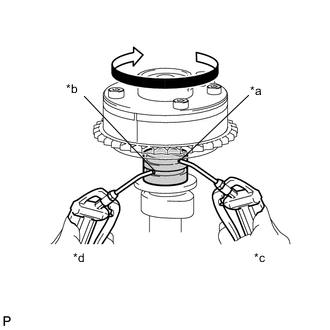
Text in Illustration *a Advance Side Path *b Retard Side Path *c Reduce Pressure *d Hold Pressure Make sure that the camshaft timing exhaust gear turns in the retard direction (clock wise) when reducing the air pressure applied to the advance side path.
Tech Tips
The lock pin is released and the camshaft timing exhaust gear turns in the retard direction.
-
When the camshaft timing exhaust gear moves to the most retarded position, release the air pressure from the advance side path, and then release the air pressure from the retard side path.
Note
Be sure to release the air pressure from the advance side path first. If the air pressure of the retard side path is released first, the camshaft timing exhaust gear may abruptly shift in the advance direction and break the lock pin or other parts.
-
-
Check for smooth rotation.
-
Turn the camshaft timing exhaust gear within its movable range (19 to 21°) 2 or 3 times, but do not turn it to the most advanced position. Make sure that the gear turns smoothly.
Note
When the air pressure is released from the advance side path, and then from the retard side path, the gear automatically returns to the most advanced position due to the advance assist spring operation and locks. Gradually release the air pressure from the retard side path before performing the smooth rotation check.
-
-
Check the lock at the most advanced position.
-
Make sure that the camshaft timing exhaust gear is locked at the most advanced position.
-
-
-
INSPECT CHAIN SUB-ASSEMBLY
-
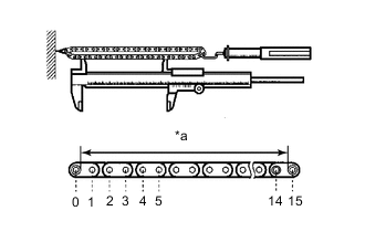
Text in Illustration *a Measurement Area Pull the chain with a force of 147 N (15 kgf, 33.1 lbf) as shown in the illustration.
-
Using a vernier caliper, measure the length of 15 links.
Maximum chain elongation 114.8 mm (4.519 in.) Tech Tips
Perform the measurement at 3 random places. Use the average of the measurements.
If the average elongation is greater than the maximum, replace the chain.
-
-
INSPECT CAMSHAFT TIMING SPROCKET (for Intake Side)
-
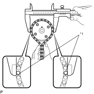
Text in Illustration *1 Chain Roller Place the chain around the camshaft timing gear.
-
Using a vernier caliper, measure the diameter of the sprocket and chain.
Minimum gear diameter (with chain) 96.8 mm (3.811 in.) Tech Tips
The vernier caliper must be in contact with the chain rollers when measuring.
If the diameter is less than the minimum, replace the chain and camshaft timing gear.
-
-
INSPECT CAMSHAFT TIMING SPROCKET (for Exhaust Side)
-
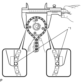
Text in Illustration *1 Chain Roller Place the chain around the camshaft timing exhaust gear.
-
Using a vernier caliper, measure the diameter of the sprocket and chain.
Minimum sprocket diameter (with chain) 96.8 mm (3.811 in.) Tech Tips
The vernier caliper must be in contact with the chain rollers when measuring.
If the diameter is less than the minimum, replace the chain and camshaft timing exhaust gear.
-
-
INSPECT CRANKSHAFT TIMING SPROCKET
-
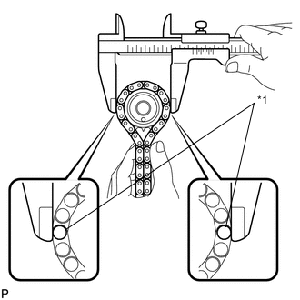
Text in Illustration *1 Chain Roller Place the chain around the crankshaft.
-
Using a vernier caliper, measure the diameter of the sprocket and chain.
Minimum gear diameter (with chain) 51.1 mm (2.012 in.) Tech Tips
The vernier caliper must be in contact with the chain rollers when measuring.
If the diameter is less than the minimum, replace the chain and crankshaft.
-
-
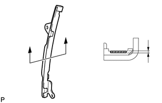
INSPECT TIMING CHAIN TENSION ARM
-
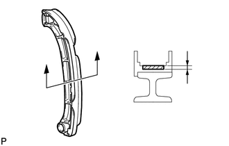
Using a vernier caliper, measure the timing chain tension arm wear.
Minimum wear 1.0 mm (0.0394 in.) If the wear is less than the minimum, replace the timing chain tension arm.
-
-
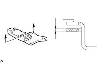
INSPECT TIMING CHAIN GUIDE
-
Using a vernier caliper, measure the timing chain guide wear.
Minimum wear 1.0 mm (0.0394 in.) If the wear is less than the minimum, replace the timing chain guide.
-
-
INSPECT NO. 2 CHAIN VIBRATION DAMPER
-
Using a vernier caliper, measure the No. 2 chain vibration damper wear.
Minimum wear 1.0 mm (0.0394 in.) If the wear is less than the minimum, replace the No. 2 chain vibration damper.
-
-
INSPECT NO. 1 CHAIN TENSIONER ASSEMBLY
-
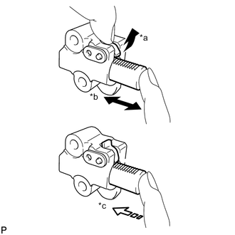
Text in Illustration *a Raise *b Move *c Lock Check that the plunger moves smoothly when the ratchet pawl is raised by hand.
-
Release the ratchet pawl, and then check that the plunger is locked in place by the ratchet pawl and does not move when pushed by hand.
-
-
INSPECT CAMSHAFT
-
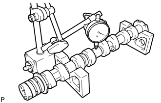
Inspect the camshaft for runout.
-
Place the camshaft on V-blocks.
-
Using a dial indicator, measure the circle runout at the center journal.
Maximum circle runout 0.04 mm (0.00157 in.) If the circle runout is greater than the maximum, replace the camshaft.
-
-
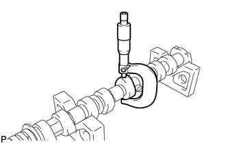
Inspect the cam lobes.
-
Using a micrometer, measure the cam lobe height.
Standard cam lobe height 41.699 to 41.7989 mm (1.6417 to 1.6456 in.) Minimum cam lobe height 41.549 mm (1.6358 in.) If the cam lobe height is less than the minimum, replace the camshaft.
-
-
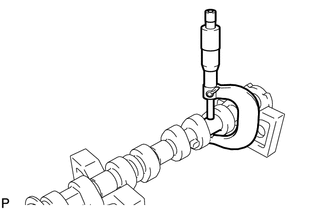
Inspect the camshaft journals.
-
Using a micrometer, measure the journal diameter.
Standard Journal Diameter Journal Position Specified Condition No. 1 34.454 to 34.470 mm (1.3565 to 1.3571 in.) Other 22.954 to 22.970 mm (0.9037 to 0.9043 in.) If the journal diameter is not as specified, check the camshaft oil clearance.
-
-
-
INSPECT NO. 2 CAMSHAFT
-
Inspect the No. 2 camshaft for runout.
-
Place the No. 2 camshaft on V-blocks.
-
Using a dial indicator, measure the circle runout at the center journal.
Maximum circle runout 0.04 mm (0.00157 in.) If the circle runout is greater than the maximum, replace the No. 2 camshaft.
-
-
Inspect the cam lobes.
-
Using a micrometer, measure the cam lobe height.
Standard cam lobe height 41.000 to 41.100 mm (1.6142 to 1.6181 in.) Minimum cam lobe height 40.85 mm (1.6083 in.) If the cam lobe height is less than the minimum, replace the No. 2 camshaft.
-
-
Inspect the camshaft journals.
-
Using a micrometer, measure the journal diameter.
Standard Journal Diameter Journal Position Specified Condition No. 1 34.454 to 34.470 mm (1.3565 to 1.3571 in.) Other 22.954 to 22.970 mm (0.9037 to 0.9043 in.) If the journal diameter is not as specified, check the camshaft oil clearance.
-
-
-
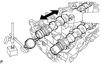
INSPECT CAMSHAFT THRUST CLEARANCE
-
Install the camshaft Click here.
-
Install the No. 2 camshaft Click here.
-
Using a dial indicator, measure the thrust clearance while moving the camshaft back and forth.
Standard Thrust Clearance Item Specified Condition Intake 0.06 to 0.2 mm (0.00236 to 0.00787 in.) Exhaust 0.06 to 0.2 mm (0.00236 to 0.00787 in.) Maximum Thrust Clearance Item Specified Condition Intake 0.215 mm (0.00846 in.) Exhaust 0.215 mm (0.00846 in.) If the thrust clearance is greater than the maximum, replace the camshaft housing. If the thrust surface is damaged, replace the camshaft.
-
-
INSPECT CAMSHAFT OIL CLEARANCE
-
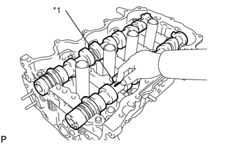
Text in Illustration *1 Plastigage Clean the bearing caps and camshaft journals.
-
Place the camshafts on the camshaft housing.
-
Lay a strip of Plastigage across each of the camshaft journals.
-
Install the camshaft bearing cap Click here.
Note
Do not turn the camshaft.
-
Remove the camshaft bearing cap Click here.
-
Text in Illustration *1 Plastigage Measure the Plastigage at its widest point.
Standard Oil Clearance Item Specified Condition No. 1 camshaft journal 0.030 to 0.067 mm (0.00118 to 0.00264 in.) Other camshaft journals 0.030 to 0.067 mm (0.00118 to 0.00264 in.) Maximum Oil Clearance Item Specified Condition No. 1 camshaft journal 0.08 mm (0.00315 in.) Other camshaft journals 0.08 mm (0.00315 in.) Note
Completely remove the Plastigage after the inspection.
If the oil clearance is greater than the maximum, replace the camshaft. If necessary, replace the camshaft housing sub-assembly.
-
-
INSPECT CYLINDER HEAD SET BOLT
-
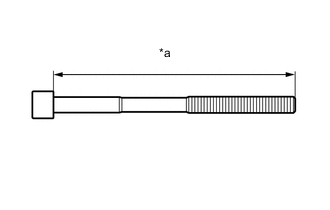
Text in Illustration *a Measurement Length Using a vernier caliper, measure the length of the cylinder head set bolt from the seat to the end.
Standard bolt length 125.3 to 126.7 mm (4.9331 to 4.9882 in.) Maximum bolt length 128.2 mm (5.047 in.) If the bolt length is greater than the maximum, replace the cylinder head set bolt.
-
-
INSPECT NO. 1 VALVE ROCKER ARM SUB-ASSEMBLY
-
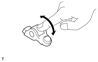
Turn the roller by hand to check that it turns smoothly.
Tech Tips
If the roller does not turn smoothly, replace the valve rocker arm sub-assembly.
-
-
INSPECT VALVE LASH ADJUSTER ASSEMBLY
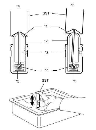
Text in Illustration *1 Tapered Path *2 Plunger *3 Low Pressure Chamber *4 Check Ball *5 High Pressure Chamber *a Correct *b Incorrect Note
-
Keep the lash adjuster free of dirt and foreign matter.
-
Only use clean engine oil.
-
Place the lash adjuster into a container filled with engine oil.
-
Insert the tip of SST into the lash adjuster plunger and use the tip to press down on the check ball inside the plunger.
- SST
- 09276-75010
-
Squeeze SST and the lash adjuster together to move the plunger up and down 5 to 6 times.
-
Check the movement of the plunger and bleed it.
OK Plunger moves up and down. Note
When bleeding the high-pressure chamber, make sure that the tip of SST is actually pressing the check ball as shown in the illustration. If the check ball is not pressed, the high-pressure chamber will not be bled.
-
After bleeding, remove SST. Then, try to quickly and firmly press the plunger by hand.
OK Plunger is very difficult to move. If the result is not as specified, replace the lash adjuster assembly.
-
-
INSPECT EXHAUST MANIFOLD CONVERTER SUB-ASSEMBLY
-
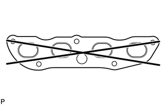
Using a straightedge and feeler gauge, measure the warpage on the contact surface of the cylinder head.
Maximum warpage 1.2 mm (0.0472 in.) Tech Tips
If the warpage is greater than the maximum, replace the exhaust manifold converter sub-assembly.
-