ENGINE ASSEMBLY INSTALLATION

CAUTION / NOTICE / HINT
Note
As the engine assembly with transaxle is extremely heavy, the engine lifter may suddenly drop if the instructions listed in the repair manual are not followed. Therefore, always follow the instructions listed in the repair manual when performing this procedure.
Tech Tips
After replacing the engine assembly, perform the "Inspection After Repairs" Click here.
PROCEDURE
-
SUSPEND ENGINE ASSEMBLY
-
Using a sling device and a chain block, suspend the engine assembly.
-
-
REMOVE ENGINE FROM ENGINE STAND
-
Remove the engine from the engine stand.
-
-
INSTALL INNER OIL SEAL (w/ Stop and Start System)
-
INSTALL RING GEAR SUB-ASSEMBLY (w/ Stop and Start System)
-
INSTALL ONE-WAY CLUTCH ASSEMBLY (w/ Stop and Start System)
-
INSTALL FLYWHEEL SUB-ASSEMBLY (w/ Stop And Start System)
-
INSTALL FLYWHEEL SUB-ASSEMBLY (for Manual Transaxle)
-
INSTALL CLUTCH DISC ASSEMBLY (for Manual Transaxle)
-
INSTALL CLUTCH COVER ASSEMBLY (for Manual Transaxle)
-
INSTALL DRIVE PLATE AND RING GEAR SUB-ASSEMBLY (for CVT)
-
INSTALL WATER BY-PASS HOSE ASSEMBLY (for CVT)
-
Connect the water by-pass hose assembly with the clamp.
-
-
INSTALL WATER HOSE SUB-ASSEMBLY (for Manual Transaxle)
Tech Tips
Use the same procedure for the water by-pass hose assembly.
-
INSTALL WATER HOSE SUB-ASSEMBLY B (for CVT)
-
Connect the water hose sub-assembly B with the clamp.
-
-
INSTALL WATER HOSE SUB-ASSEMBLY B (for Manual Transaxle)
Tech Tips
Use the same procedure for the water hose subassembly B.
-
INSTALL ENGINE WIRE
-
Install the engine wire to the cylinder head cover with the 2 nuts.
- Torque:
- 8.4 N*m { 86 kgf*cm, 74 in.*lbf }
-
Install the 2 ground wires to the cylinder head with the 2 bolts.
- Torque:
- 8.4 N*m { 86 kgf*cm, 74 in.*lbf }
-
-
INSTALL GENERATOR ASSEMBLY
-
REMOVE ENGINE HANGER
-
Remove the 2 bolts and 2 engine hangers.
-
-
INSTALL CONTINUOUSLY VARIABLE TRANSAXLE ASSEMBLY (for CVT)
-
INSTALL MANUAL TRANSAXLE ASSEMBLY (for Manual Transaxle)
-
INSTALL ENGINE ASSEMBLY WITH TRANSAXLE
-
Install the engine mounting insulator sub-assembly RH with the 3 bolts.
Tech Tips
Only perform this procedure when replacement of the engine mounting insulator sub-assembly RH is necessary.
- Torque:
- 52 N*m { 530 kgf*cm, 38 ft.*lbf }
-
Install the engine mounting insulator LH with the 5 bolts.
Tech Tips
Only perform this procedure when replacement of the engine mounting insulator LH is necessary.
- Torque:
- 52 N*m { 530 kgf*cm, 38 ft.*lbf }
-
Set the engine assembly with transaxle on the engine lifter.
-
Operate the engine lifter and lift the engine assembly with transaxle into the position where the engine mounting insulators RH and LH can be installed.
CAUTION:
Do not raise the engine more than necessary. If the engine is raised excessively, the vehicle may also be lifted up.
Note
-
Make sure that the engine is clear of all wiring and hoses.
-
While raising the engine into the vehicle, do not allow it to contact the vehicle.
-
-
Install the engine mounting insulator LH with the through bolt and nut.
- Torque:
- 52 N*m { 530 kgf*cm, 38 ft.*lbf }
-
Install the engine mounting insulator sub-assembly RH with the bolt and 2 nuts.
- Torque:
- 52 N*m { 530 kgf*cm, 38 ft.*lbf }
-
Provisionally install the front suspension crossmember onto the body with the 6 bolts.
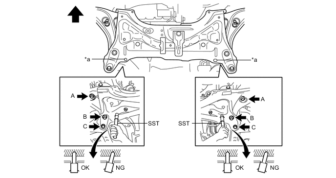
Text in Illustration *a Datum Hole - - 
Front of the Vehicle - - -
By inserting SST into the datum holes in the front suspension crossmember RH and LH alternately, tighten bolts A, B and C on both sides to the specified torque, in several steps.
- SST
- 09670-00010
- Torque:
- Bolt A
- 87 N*m { 887 kgf*cm, 64 ft.*lbf }
- Bolt B
- 151 N*m { 1540 kgf*cm, 111 ft.*lbf }
- Bolt C
- 98 N*m { 999 kgf*cm, 72 ft.*lbf }
Note
-
Insert SST into the datum hole in a vertical orientation.
-
If SST cannot be inserted into the datum hole vertically, loosen all the bolts and then insert SST again.
-
-
INSTALL DRIVE PLATE AND TORQUE CONVERTER CLUTCH SETTING BOLT
-
Clean and degrease the 6 drive plate and torque converter setting bolts.
-
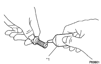
Text in Illustration *1 Adhesive Apply a few drops of adhesive to 2 or 3 threads at the end of each of the 6 torque converter clutch setting bolts.
Adhesive Toyota Genuine Adhesive 1324, Three Bond 1324 or equivalent -
Use SST to hold the crankshaft pulley in place.
- SST
- 09960-10010 ( 09962-01000, 09963-01000 )
-
Install the 6 torque converter set bolts.
- Torque:
- 28 N*m { 286 kgf*cm, 21 ft.*lbf }
Note
First install the black-colored bolt, and then the remaining 5 silver-colored bolts.
-
-
INSTALL STARTER ASSEMBLY (w/ Stop And Start System)
-
INSTALL STARTER ASSEMBLY (w/o Stop And Start System)
-
INSTALL FLYWHEEL HOUSING SIDE COVER
-
INSTALL FRONT EXHAUST PIPE ASSEMBLY
-
INSTALL FRONT FLOOR CENTER BRACE
-
Install the front floor center brace with the 2 bolts.
- Torque:
- 30 N*m { 306 kgf*cm, 22 ft.*lbf }
-
-
INSTALL FRONT DRIVE SHAFT ASSEMBLY
-
INSTALL DRIVE SHAFT HEAT INSULATOR SUB-ASSEMBLY
-
Install the drive shaft heat insulator sub-assembly with the 2 bolts.
- Torque:
- 24 N*m { 245 kgf*cm, 18 ft.*lbf }
-
-
INSTALL NO. 1 STEERING COLUMN HOLE COVER SUB-ASSEMBLY
-
INSTALL STEERING SLIDING YOKE SUB-ASSEMBLY
-
INSTALL COLUMN HOLE COVER SILENCER SHEET
-
CONNECT ENGINE WIRE
-
Connect the connector to the negative battery terminal.
-
Connect the 2 connectors to the positive battery terminal.
-
Install the ground wire to the body with the bolt.
- Torque:
- 8.4 N*m { 86 kgf*cm, 74 in.*lbf }
-
Engage the 3 clamps and connect the 2 connectors to the engine room relay block.
-
Install the engine room relay block cover.
-
Check that the engine wire is connected between the body and engine assembly with transaxle.
-
-
CONNECT ECM CONNECTOR (for LHD)
-
Connect the engine wire connector to the ECM.
-
Engage the clamp and install the engine wire to the wire harness clamp bracket.
-
-
CONNECT ECM CONNECTOR (for RHD)
-
Connect the engine wire connector to the ECM.
-
-
INSTALL COMPRESSOR ASSEMBLY WITH PULLEY (w/ Air Conditioning System)
-
INSTALL CLUTCH HOSE (for Manual Transaxle)
-
INSTALL TRANSMISSION CONTROL CABLE ASSEMBLY (for CVT)
(See page MULTIDRIVE / CVT (K310) > TRANSMISSION CONTROL CABLE > INSTALLATION > INSTALL TRANSMISSION CONTROL CABLE ASSEMBLY)
-
INSTALL TRANSMISSION CONTROL CABLE ASSEMBLY (for Manual Transaxle)
-
CONNECT FUEL TUBE SUB-ASSEMBLY
-
INSTALL EFI FUEL PIPE CLAMP
-
INSTALL WATER HOSE SUB-ASSEMBLY B
-
Connect the water hose subassembly B with the clamp.
-
-
INSTALL INLET HEATER WATER HOSE A
-
Connect the inlet heater water hose A with the clamp.
-
-
CONNECT NO. 2 RADIATOR HOSE
-
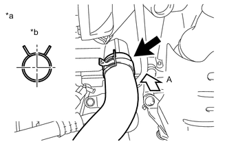
Text in Illustration *a View A *b Upper Side Connect the No. 2 radiator hose with the clamp.
-
-
CONNECT NO. 1 RADIATOR HOSE
-
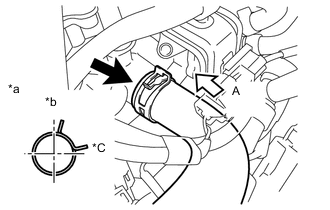
Text in Illustration *a View A *b Upper Side *c Rear Side Connect the No. 1 radiator hose with the clamp.
-
-
CONNECT UNION TO CONNECTOR TUBE HOSE
-
Connect the union to connector tube hose to the intake manifold.
-
-
INSTALL AIR CLEANER AND HOSE ASSEMBLY
-
Connect the air cleaner hose to the throttle body.
-
Connect the No. 2 ventilation hose to the air cleaner hose.
-
Connect the No. 1 fuel vapor feed hose and the No. 2 fuel vapor feed hose to the No. 1 vacuum switching valve assembly.
-
Connect the No. 1 vacuum switching valve assembly connector and engage the clamp.
-
Install the air cleaner case to the cylinder head cover with the 2 bolts.
- Torque:
- 7.8 N*m { 80 kgf*cm, 69 in.*lbf }
-
Connect the intake mass air flow meter connector and engage the clamp.
-
-
INSTALL INLET NO. 1 AIR CLEANER
-
Install the inlet No. 1 air cleaner to the cylinder head cover with the bolt.
- Torque:
- 7.8 N*m { 80 kgf*cm, 69 in.*lbf }
-
-
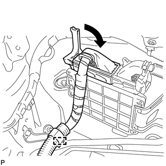
INSTALL BATTERY CARRIER
-
Install the battery carrier with the 5 bolts.
- Torque:
- 17 N*m { 173 kgf*cm, 13 ft.*lbf }
-
Engage the 3 clamps and connect the wire harness to the battery carrier.
-
-
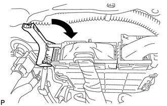
INSTALL BATTERY TRAY
-
Install the battery tray to the battery carrier.
-
-
INSTALL BATTERY
-
Install the battery to the battery tray.
-
Install the battery carrier clamp with the nut.
- Torque:
- 3.5 N*m { 36 kgf*cm, 31 in.*lbf }
-
Connect the cable to the positive (+) battery terminal.
- Torque:
- 5.4 N*m { 55 kgf*cm, 48 in.*lbf }
-
-
INSTALL FAN AND GENERATOR V BELT
-
INSTALL OUTER COWL TOP PANEL (for LHD)
-
Install the outer cowl top panel with the 6 bolts.
- Torque:
- 7.0 N*m { 71 kgf*cm, 62 in.*lbf }
-
-
INSTALL OUTER COWL TOP PANEL (for RHD)
Tech Tips
Use the same procedure for the RH and LH sides.
-
INSTALL INNER COWL TOP TO COWL BRACE (for LHD)
-
Install the cowl top to cowl brace with the 2 bolts.
- Torque:
- 7.0 N*m { 71 kgf*cm, 62 in.*lbf }
-
-
INSTALL INNER COWL TOP TO COWL BRACE (for RHD)
Tech Tips
Use the same procedure for the RH and LH sides.
-
INSTALL INNER COWL TOP REINFORCEMENT (for LHD)
-
INSTALL INNER LOWER COWL TOP REINFORCEMENT (for RHD)
-
INSTALL COWL TOP INSIDE CORNER PANEL LH (for LHD)
-
INSTALL COWL TOP INSIDE CORNER PANEL RH (for RHD)
-
INSTALL FRONT NO. 1 VENTILATOR SEAL
-
Engage the clip and install the front No. 1 ventilator seal.
-
-
INSTALL FRONT AIR SHUTTER SEAL RH
Tech Tips
Use the same procedure for the front No. 1 ventilator seal.
-
INSTALL WINDSHIELD WIPER LINK ASSEMBLY
-
INSTALL FRONT WHEELS
- Torque:
- 103 N*m { 1050 kgf*cm, 76 ft.*lbf }
-
CONNECT CABLE TO NEGATIVE BATTERY TERMINAL
- Torque:
- 5.4 N*m { 55 kgf*cm, 48 in.*lbf }
-
ADD ENGINE OIL
-
ADD ENGINE COOLANT
-
ADD CONTINUOUSLY VARIABLE TRANSAXLE FLUID (for CVT)
-
ADD MANUAL TRANSAXLE OIL (for Manual Transaxle)
-
BLEED CLUTCH PIPE LINE (for Manual Transmission)
-
INSPECT CONTINUOUSLY VARIABLE TRANSAXLE FLUID (for CVT)
-
INSPECT FOR FUEL LEAK
-
INSPECT ENGINE OIL LEVEL
-
INSPECT FOR ENGINE OIL LEAK
-
INSPECT FOR ENGINE COOLANT LEAK
-
INSPECT RESERVOIR TANK ENGINE COOLANT LEVEL
-
INSPECT CONTINUOUSLY VARIABLE TRANSAXLE FLUID LEAK (for CVT)
-
INSPECT MANUAL TRANSAXLE OIL LEAK (for Manual Transaxle)
-
INSPECT FOR CLUTCH FLUID LEAK (for Manual Transmission)
-
INSPECT FOR EXHAUST GAS LEAK
-
INSPECT IGNITION TIMING
-
INSPECT ENGINE IDLING SPEED
-
INSPECT CO/HC
-
INSTALL NO. 1 ENGINE COVER
-
Engage the 3 clamps and install the No. 1 engine cover to the cylinder head cover.
-
-
INSPECT AND ADJUST FRONT WHEEL ALIGNMENT
-
INSTALL ENGINE UNDER COVER RH
-
Install the engine under cover RH with the screw and 2 bolts.
- Torque:
- 5.0 N*m { 51 kgf*cm, 44 in.*lbf }
-
-
INSTALL ENGINE UNDER COVER LH
-
Install the engine under cover LH with the 3 screws and 3 bolts.
- Torque:
- 5.0 N*m { 51 kgf*cm, 44 in.*lbf }
-
-
CHECK SPEED SENSOR SIGNAL (w/o VSC)
-
CHECK SPEED SENSOR SIGNAL (w/ VSC)