ENGINE ASSEMBLY INSTALLATION

CAUTION / NOTICE / HINT
Note
As the engine assembly with transaxle is extremely heavy, the engine lifter may suddenly drop if the instructions listed in the repair manual are not followed. Therefore, always follow the instructions listed in the repair manual when performing this procedure.
Tech Tips
After replacing the engine assembly, perform the "Inspection After Repairs" Click here.
PROCEDURE
-
REMOVE ENGINE STAND
-
Using a chain block and sling device, secure the engine assembly.
Note
Make sure that the sling angle is correct to prevent the engine assembly and engine hangers from being damaged or deformed.
-
Remove the engine stand from the engine assembly.
-
-
INSTALL DRIVE PLATE AND RING GEAR SUB-ASSEMBLY
-
INSTALL CONTINUOUSLY VARIABLE TRANSAXLE ASSEMBLY
-
CONNECT WATER BY-PASS HOSE
-
INSTALL STARTER ASSEMBLY
-
INSTALL FLYWHEEL HOUSING SIDE COVER
-
INSTALL ENGINE WIRE
-
Connect all the wire harnesses and connectors.
-
Install the 2 ground bolts.
- Torque:
- 8.5 N*m { 87 kgf*cm, 75 in.*lbf }
-
-
INSTALL VENTILATION HOSE
-
Connect the ventilation hose with the 2 clips.
-
-
REMOVE ENGINE HANGER
-
Remove the 2 bolts and the 2 engine hangers.
-
-
INSTALL WIRE HARNESS CLAMP BRACKET
-
Install the wire harness clamp bracket with the bolt.
- Torque:
- 30 N*m { 306 kgf*cm, 22 ft.*lbf }
-
-
INSTALL ENGINE MOUNTING INSULATOR SUB-ASSEMBLY RH
-
Install the engine mounting insulator sub-assembly RH with the 3 bolts.
- Torque:
- 52 N*m { 530 kgf*cm, 38 ft.*lbf }
Tech Tips
Only perform this procedure when replacement of the engine mounting insulator sub-assembly RH is necessary.
-
-
INSTALL TRANSVERSE ENGINE ENGINE MOUNTING INSULATOR
-
Install the transverse engine engine mounting insulator with the 5 bolts.
- Torque:
- 52 N*m { 530 kgf*cm, 38 ft.*lbf }
Tech Tips
Only perform this procedure when replacement of the transverse engine engine mounting insulator is necessary.
-
-
INSTALL ENGINE ASSEMBLY WITH TRANSAXLE
-
Using a sling device and chain block, set the engine assembly with transaxle on the engine lifter.
Note
-
Place the height adjustment and plate lift attachments so that the engine assembly with transaxle is level.
-
Securely support the engine assembly with transaxle to prevent it from turning upside down until it is secured to the engine lifter.
-
To prevent the No. 2 oil pan sub-assembly from deforming, do not place any attachments under the No. 2 oil pan sub-assembly of the engine assembly.
-
Do not place any attachments onto the drain plug and rear cover plug of the transaxle assembly.
-
Make sure to support the engine assembly with transaxle securely to prevent it from falling.
-
-
Operate the engine lifter and lift the engine assembly with transaxle and front suspension crossmember to the position where the engine mounting insulator sub-assembly RH and transverse engine engine mounting insulator can be installed.
CAUTION:
Do not raise the engine assembly with transaxle more than necessary. If the engine assembly with transaxle is raised excessively, the vehicle may also be lifted up.
Note
-
Make sure that the engine assembly with transaxle is clear of all wiring and hoses.
-
While raising the engine assembly with transaxle into the vehicle, do not allow it to contact the vehicle.
-
-
Install the transverse engine engine mounting insulator with the through bolt and nut.
- Torque:
- 52 N*m { 530 kgf*cm, 38 ft.*lbf }
Tech Tips
While fixing the nut in place, tighten the bolt.
-
Install the engine mounting insulator sub-assembly RH with the bolt and 2 nuts.
- Torque:
- 52 N*m { 530 kgf*cm, 38 ft.*lbf }
-
Provisionally install the front suspension crossmember onto the body with the 6 bolts.
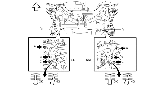
Text in Illustration *a Datum Hole - - 
Front of the Vehicle - - -
By inserting SST into the datum holes in the front suspension crossmember RH and LH alternately, tighten bolts A, B and C on both sides to the specified torque, in several steps.
- SST
- 09670-00010
- Torque:
- Bolt A
- 87 N*m { 887 kgf*cm, 64 ft.*lbf }
- Bolt B
- 151 N*m { 1540 kgf*cm, 111 ft.*lbf }
- Bolt C
- 98 N*m { 999 kgf*cm, 72 ft.*lbf }
Note
-
Insert SST into the datum hole in a vertical orientation.
-
If SST cannot be inserted into the datum hole vertically, loosen all the bolts and then insert SST again.
-
-
INSTALL DRIVE PLATE AND TORQUE CONVERTER ASSEMBLY SETTING BOLT
-
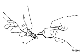
Text in Illustration *1 Adhesive Apply a few drops of adhesive to 2 or 3 threads at the end of each of the 6 drive plate and torque converter assembly setting bolts.
Adhesive Toyota Genuine Adhesive 1324, Three Bond 1324 or equivalent Note
Install the bolt within 3 minutes of applying adhesive.
-
Use SST to hold the crankshaft pulley in place.
- SST
- 09960-10010 ( 09962-01000, 09963-01000 )
Note
Be careful not let SST slip during the work.
-
Install the 6 drive plate and torque converter assembly setting bolts.
- Torque:
- 28 N*m { 286 kgf*cm, 21 ft.*lbf }
Note
First install the black-colored bolt, and then the remaining 5 silver-colored bolts.
-
-
INSTALL FLYWHEEL HOUSING UNDER COVER
-
Install the flywheel housing under cover.
-
-
INSTALL FRONT DRIVE SHAFT ASSEMBLY
-
INSTALL FRONT EXHAUST PIPE ASSEMBLY
-
INSTALL FRONT FLOOR CENTER BRACE
-
CONNECT HEATED OXYGEN SENSOR
-
INSTALL REAR CONSOLE BOX
-
INSTALL NO. 1 STEERING COLUMN HOLE COVER SUB-ASSEMBLY
-
INSTALL STEERING SLIDING YOKE SUB-ASSEMBLY
-
INSTALL COLUMN HOLE COVER SILENCER SHEET
-
CONNECT ENGINE WIRE
-
Install the transaxle earth wire of the engine room wire harness with the bolt.
- Torque:
- 13 N*m { 133 kgf*cm, 10 ft.*lbf }
-
Connect the 2 connectors to the positive (+) battery terminal.
-
Engage the 3 clamps and connect the 2 connectors to the engine room relay block.
-
Connect the engine wire harness connector to the ECM.
-
Check that the engine wire is connected between the body and engine assembly with transaxle.
-
-
INSTALL COMPRESSOR ASSEMBLY WITH PULLEY
-
CONNECT INLET HEATER WATER HOSE A
-
Connect the inlet heater water hose A with the clamp.
-
-
CONNECT OUTLET HEATER WATER HOSE A
-
Connect the outlet heater water hose A with the clamp.
-
-
CONNECT UNION TO CHECK VALVE HOSE
-
Connect the union to check valve hose to the booster vacuum tube.
-
-
CONNECT FUEL TUBE SUB-ASSEMBLY
-
Connect the fuel tube to the fuel pipe.
CAUTION:
Align the fuel tube connector with the pipe, then push the fuel tube connector in until the retainer makes a click sound. If the connection is tight, apply a small amount of engine oil or spindle oil to the tip of the pipe. After connecting, pull the pipe and connector to make sure that they are securely connected.
-
-
INSTALL NO. 2 FUEL PIPE CLAMP
-
Install the No. 2 fuel pipe clamp.
-
-
INSTALL TRANSMISSION CONTROL CABLE ASSEMBLY
-
CONNECT NO. 2 RADIATOR HOSE
-
Connect the No. 2 radiator hose to the water inlet with the hose clamp.
-
-
CONNECT RADIATOR RESERVOIR TANK HOSE
-
Connect the radiator reservoir tank hose to the water filler sub-assembly.
-
-
CONNECT NO. 3 RADIATOR HOSE
-
Connect the No. 3 radiator hose to the water filler sub-assembly.
-
-
CONNECT FUEL VAPOR FEED HOSE ASSEMBLY
-
Connect the fuel vapor feed hose assembly with the 2 clips.
-
-
INSTALL BATTERY CARRIER
-
Install the battery carrier with the 5 bolts.
- Torque:
- 17 N*m { 173 kgf*cm, 13 ft.*lbf }
-
Engage the 7 clamps to the battery carrier.
-
-
INSTALL AIR CLEANER BRACKET
-
Install the air cleaner bracket with the 2 bolts.
- Torque:
- 20 N*m { 199 kgf*cm, 14 ft.*lbf }
-
Connect the wire harness clamp to the air cleaner bracket.
-
-
INSTALL AIR CLEANER ASSEMBLY
-
Install the air cleaner case with the 2 bolts.
- Torque:
- 7.8 N*m { 80 kgf*cm, 69 in.*lbf }
-
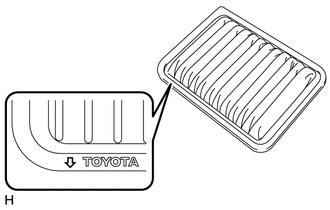
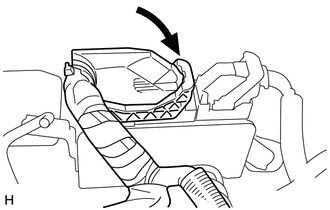
Face the arrow shown in the illustration towards the front of the vehicle and install the air cleaner element.
-
Install the air cleaner cap and air cleaner hose with the 2 clamps.
-
Tighten the air cleaner hose clamp.
- Torque:
- 3.0 N*m { 31 kgf*cm, 27 in.*lbf }
-
Engage the clamp and connect the No. 1 vacuum switching valve connector and No.2 fuel vapor feed hose assembly.
-
Engage the guide and 2 clips and connect the fuel vapor feed hose assembly.
-
Engage the clamp and connect the intake mass air flow meter connector.
-
-
INSTALL FAN AND GENERATOR V BELT
-
INSPECT FAN AND GENERATOR V BELT
-
INSTALL BATTERY TRAY
-
Install the battery tray to the battery carrier.
-
-
INSTALL BATTERY
-
Install the battery onto the vehicle with the battery carrier clamp.
- Torque:
- 3.5 N*m { 36 kgf*cm, 31 in.*lbf }
-
Connect the positive (+) cable to the positive (+) battery terminal.
- Torque:
- 5.4 N*m { 55 kgf*cm, 48 in.*lbf }
-
-
INSTALL FRONT WHEELS
- Torque:
- 103 N*m { 1050 kgf*cm, 76 ft.*lbf }
-
CONNECT CABLE TO NEGATIVE BATTERY TERMINAL
- Torque:
- 5.4 N*m { 55 kgf*cm, 48 in.*lbf }
Note
When disconnecting the cable, some systems need to be initialized after the cable is reconnected Click here.
-
ADD ENGINE OIL
-
ADD COOLANT
-
ADD CONTINUOUSLY VARIABLE TRANSAXLE FLUID
-
INSPECT FOR FUEL LEAK
-
INSPECT ENGINE OIL LEVEL
-
INSPECT FOR ENGINE OIL LEAK
-
INSPECT FOR ENGINE COOLANT LEAK
-
INSPECT RESERVOIR TANK ENGINE COOLANT LEVEL
-
INSPECT CONTINUOUSLY VARIABLE TRANSAXLE FLUID
-
INSPECT FOR EXHAUST GAS LEAK
-
INSPECT IGNITION TIMING
-
INSPECT ENGINE IDLE SPEED
-
INSPECT CO/HC
-
INSPECT AND ADJUST FRONT WHEEL ALIGNMENT
-
INSTALL ENGINE UNDER COVER RH
-
Install the engine under cover RH with the screw and 2 bolts.
- Torque:
- 5.0 N*m { 51 kgf*cm, 44 in.*lbf }
-
-
INSTALL ENGINE UNDER COVER LH
-
Install the engine under cover LH with the 3 screws and 3 bolts.
- Torque:
- 5.0 N*m { 51 kgf*cm, 44 in.*lbf }
-
-
INSPECT ABS SENSOR SIGNAL