CYLINDER HEAD REPLACEMENT

PROCEDURE
-
REPLACE INTAKE VALVE GUIDE BUSHING
-
Heat the cylinder head to between 80 and 100°C (176 and 212°F).
-
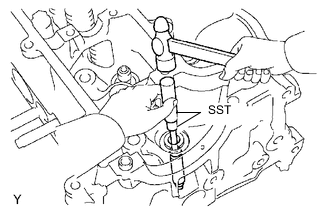
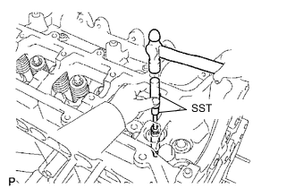
Using SST and a hammer, tap out the valve guide bushing to the combustion chamber side.
- SST
- 09201-10000
- 09950-70010
-
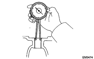
Using a caliper gauge, measure the bushing bore diameter of the cylinder head.
Diameter 10.985 to 11.006 mm (0.4325 to 0.4333 in.) Tech Tips
-
If the bushing bore diameter is as specified, install the standard bushing.
-
If the bushing bore diameter is not as specified, correct it to 11.035 to 11.056 mm (0.4345 to 0.4353 in.) and install the oversize bushing.
Bushing Size Bushing Bore Diameter mm (in.) Standard Standard 10.985 to 11.006 (0.4325 to 0.4333) Over size (0.05) Over size 11.035 to 11.056 (0.4345 to 0.4353)
-
-
Heat the cylinder head to between 80 and 100°C (176 and 212°F).
-
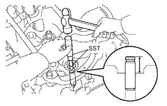
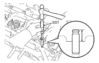
Using SST and a hammer, tap in a new valve guide bushing to the specified protrusion height.
- SST
- 09201-10000
- 09950-70010
Protrusion height 15.9 to 16.7 mm (0.626 to 0.657 in.) -
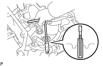
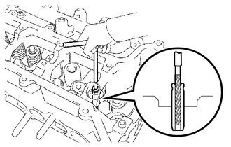
Using a reamer, ream the inside of the valve guide bushing to the specified oil clearance between the valve guide bushing and valve stem.
Standard oil clearance 0.025 to 0.060 mm (0.0010 to 0.0024 in.)
-
-
REPLACE EXHAUST VALVE GUIDE BUSHING
-
Heat the cylinder head to between 80 and 100°C (176 and 212°F).
-
Using SST and a hammer, tap out the valve guide bushing to the combustion camber side.
- SST
- 09201-10000
- 09950-70010
-
Using a caliper gauge, measure the bushing bore diameter of the cylinder head.
Diameter 10.985 to 11.006 mm (0.4325 to 0.4333 in.) Tech Tips
-
If the valve guide bushing bore diameter is as specified, install the standard valve guide bushing.
-
If the valve guide bushing bore diameter is not as specified, correct it to 11.035 to 11.056 mm (0.4345 to 0.4353 in.) and install the oversize valve guide bushing.
Bushing size Bushing Bore Diameter mm (in.) Standard Standard 10.985 to 11.006 (0.4325 to 0.4333) Over size (0.05) Over size 11.035 to 11.056 (0.4345 to 0.4353)
-
-
Heat the cylinder head to between 80 and 100°C (176 and 212°F).
-
Using SST and a hammer, tap in a new valve guide bushing to the specified protrusion height.
- SST
- 09201-10000
- 09950-70010
Protrusion height 15.9 to 16.7 mm (0.626 to 0.657 in.) -
Using a reamer, ream the inside of the valve guide bushing to the specified oil clearance between the valve guide bushing and valve stem.
Standard oil clearance 0.030 to 0.065 mm (0.0012 to 0.0023 in.)
-
-
REPLACE RING PIN
-
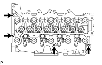
Remove the 4 ring pins indicated in the illustration.
-
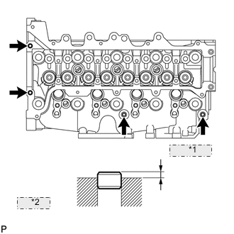
*1 4.0 to 5.0 (0.157 to 0.197) *2 mm (in.) Using a plastic-faced hammer, tap in 4 new ring pins to the specified protrusion height.
-
-
REPLACE STRAIGHT PIN
-
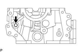
Remove the straight pin indicated in the illustration.
-
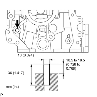
Using a plastic-faced hammer, tap in a new straight pin to the specified protrusion height.
-
-
REPLACE STUD BOLT
-
Using "TORX" socket wrenches E6, E8 and E10, remove the 17 stud bolts.
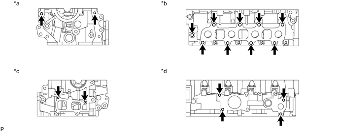
Text in Illustration *a Front Side *b Exhaust Side *c Rear Side *d Intake Side -
Using "TORX" socket wrenches E6, E8 and E10, install the 17 stud bolts.
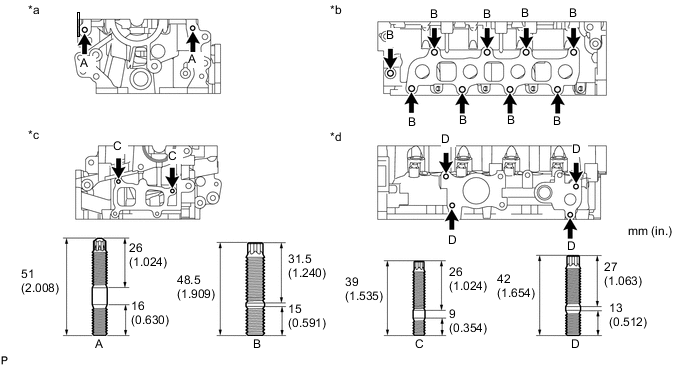
- Torque:
- Stud Bolt A, D
- 10 N*m { 102 kgf*cm, 7 ft.*lbf }
- Stud Bolt B
- 15 N*m { 153 kgf*cm, 11 ft.*lbf }
- Stud Bolt C
- 5.0 N*m { 51 kgf*cm, 44 in.*lbf }
Text in Illustration *a Front Side *b Exhaust Side *c Rear Side *d Intake Side
-