ENGINE UNIT INSTALLATION

PROCEDURE
-
INSTALL OIL PAN COVER
-
Install the oil pan cover with the 2 bolts and 2 washer plates.
- Torque:
- 7.0 N*m { 71 kgf*cm, 62 in.*lbf }
-
-
INSTALL NO. 2 OIL PAN COVER SILENCER
-
Install the No. 2 oil pan cover silencer with the 2 washer plates and 2 bolts.
- Torque:
- 7.0 N*m { 71 kgf*cm, 62 in.*lbf }
-
-
INSTALL NO. 5 ENGINE COVER
-
Install the No. 5 engine cover with the 2 bolts and 2 washer plates.
- Torque:
- 7.0 N*m { 71 kgf*cm, 62 in.*lbf }
-
-
INSTALL HARNESS BRACKET
-
Install the 2 harness brackets with the 2 bolts.
- Torque:
- 8.4 N*m { 85 kgf*cm, 74 in.*lbf }
-
-
INSTALL V-RIBBED BELT TENSIONER ASSEMBLY
-
Install the V-ribbed belt tensioner with the 2 bolts.
- Torque:
- 24 N*m { 245 kgf*cm, 18 ft.*lbf }
-
-
INSTALL CAMSHAFT POSITION SENSOR
-
Install the camshaft position sensor with the bolt.
- Torque:
- 7.0 N*m { 71 kgf*cm, 62 in.*lbf }
-
-
INSTALL VACUUM PUMP ASSEMBLY
-
Install 2 new O-rings to the vacuum pump.
-
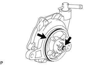
Apply a small amount of engine oil to the 2 O-rings.
-
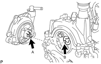
Install the vacuum pump so that the coupling teeth A on the side of the vacuum pump can engage with the tip groove of camshaft B.
-
Install the vacuum pump with the 2 new bolts.
- Torque:
- 21 N*m { 214 kgf*cm, 15 ft.*lbf }
-
-
INSTALL INLET WATER PIPE
-
Install the inlet water pipe with the 2 bolts.
- Torque:
- 9.0 N*m { 92 kgf*cm, 80 in.*lbf }
-
-
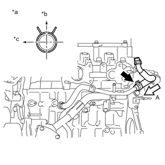
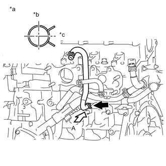
INSTALL INLET WATER HOSE LH
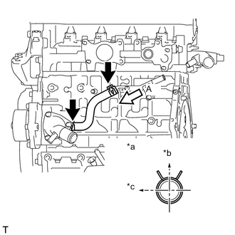
Text in Illustration *a View A *b Upper *c LH
-
Install the inlet water hose LH.
Tech Tips
The clip at the inlet water housing can be installed in any orientation, as long as it does not contact any of the surrounding parts.
-
-
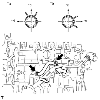
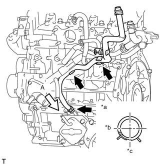
INSTALL INLET WATER HOSE RH
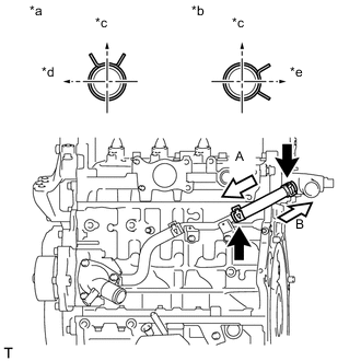
Text in Illustration *a View A *b View B *c Upper *d LH *e Rear
-
Install the inlet water hose RH.
-
-
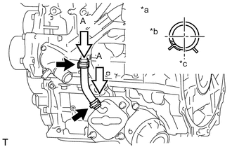
INSTALL WATER BY-PASS PIPE SUB-ASSEMBLY
-
Install a new O-ring to the water by-pass pipe.
Note
Apply water to all around of the O-ring's inserting hole surface of the water inlet housing before installing the water by-pass pipe.
-
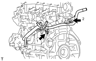
Install the water by-pass pipe with the 2 bolts, in the order shown in the illustration.
- Torque:
- 9.0 N*m { 92 kgf*cm, 80 in.*lbf }
-
Install the 2 hose clamps.
-
-
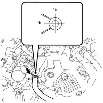
INSTALL WATER BY-PASS HOSE
Text in Illustration *a View A *b View B *c Upper *d Front *e RH
-
Install the water by-pass hose.
-
-
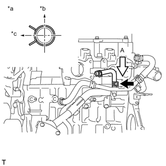
INSTALL NO. 2 WATER BY-PASS HOSE
Text in Illustration *a View A *b Upper *c LH
-
Install the No. 2 water by-pass hose.
-
-
INSTALL NO. 3 WATER BY-PASS HOSE
Text in Illustration *a View A *b Front *c LH
-
Install the No. 3 water by-pass hose.
-
-
INSTALL NO. 4 WATER BY-PASS HOSE
Text in Illustration *a View A *b Upper *c Rear
-
Install the No. 4 water by-pass hose.
-
-
INSTALL NO. 2 OIL COOLER HOSE
Text in Illustration *a View A *b Front *c LH
-
Connect the 3 hose clamps and install the No. 2 oil cooler hose.
Note
Align the oil cooler hose paint mark with the clamp center.
-
Install the 2 hose clamps.
Note
Align the oil cooler hose paint mark with the clamp center.
-
-
INSTALL OIL COOLER HOSE
Text in Illustration *a View A *b Front *c LH
-
Install the oil cooler hose.
-
-
INSTALL NO. 2 CYLINDER HEAD COVER
-
Install the No. 2 cylinder head cover.
-
-
INSTALL NO. 1 INTAKE MANIFOLD INSULATOR
-
Install the No. 1 intake manifold insulator.
-
-
INSTALL COMMON RAIL ASSEMBLY
-
Install the common rail with the 2 bolts.
- Torque:
- 21 N*m { 214 kgf*cm, 15 ft.*lbf }
-
-
INSTALL SUPPLY PUMP DRIVE COUPLING
-
TEMPORARILY TIGHTEN SUPPLY PUMP ASSEMBLY
Note
When installing, clean the seal surfaces of the fuel inlet pipe, supply pump and common rail.
-
Apply a light coat of engine oil to a new O-ring.
-
Install the O-ring onto the supply pump.
-
Temporarily tighten the supply pump with the 3 bolts.
-
Text in Illustration *a Upper *b Front Connect the No. 1 fuel hose.
-
-
INSTALL FUEL INLET PIPE SUB-ASSEMBLY
-
INSTALL NO. 2 FUEL HOSE
-
Install the No. 2 fuel hose.
-
-
INSTALL INJECTION NOZZLE SEAT
-
INSTALL INJECTOR ASSEMBLY
-
INSTALL NOZZLE HOLDER CLAMP SEAT
-
INSTALL NO. 1 NOZZLE HOLDER CLAMP
-
INSTALL NOZZLE LEAKAGE PIPE ASSEMBLY
-
Install the nozzle leakage pipe into each injector.
-
Make sure the lock bush is at top position.
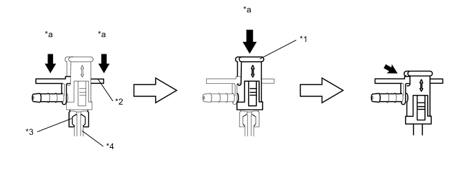
Text in Illustration *1 Lock Bush *2 Return Plug *3 Rest Arm *4 Injector *a Push - - -
Insert the rest arm into the injector and push both sides of the return plug until the rest arm engages with the injector, as shown in the illustration.
Tech Tips
Push the nozzle leakage pipe until it makes a click sound.
-
Push the lock bush until it fits with the return plug, as shown in the illustration.
-
-
Connect the nozzle leakage pipe and install new retainer spring onto the supply pump.
-
-
INSTALL NOZZLE LEAKAGE PIPE SET CLAMP
-
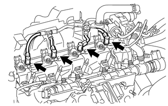
Install the 3 nozzle leakage pipe set clamps.
-
-
INSTALL NO. 2 INTAKE MANIFOLD INSULATOR
-
INSTALL GLOW PLUG ASSEMBLY
-
Clean the glow plug installation holes in the cylinder head.
-
Install the 4 glow plug assemblies.
- Torque:
- 13 N*m { 127 kgf*cm, 9 ft.*lbf }
-
-
INSTALL NO. 1 GLOW PLUG CONNECTOR
-
Install the No. 1 glow plug connector with the 4 nuts.
- Torque:
- 2.2 N*m { 22 kgf*cm, 19 in.*lbf }
-
Install the 4 screw grommet.
-
-
INSTALL NO. 1 INJECTION PIPE SUB-ASSEMBLY
-
INSTALL NO. 2 INJECTION PIPE SUB-ASSEMBLY
-
INSTALL NO. 3 INJECTION PIPE SUB-ASSEMBLY
-
INSTALL INTAKE AIR CONNECTOR WITH DIESEL THROTTLE BODY ASSEMBLY
-
Install the new gasket to the cylinder head.
-
Install the intake air connector with the diesel throttle body with the 2 bolts and 2 nuts.
- Torque:
- 23 N*m { 235 kgf*cm, 17 ft.*lbf }
-
Connect the hose clamp.
-
-
INSTALL NO. 1 OIL HOSE
-
Install the No. 1 oil hose.
-
Connect the No. 1 oil hose.
-
-
INSTALL OIL LEVEL DIPSTICK GUIDE SUB-ASSEMBLY
-
Install a new O-ring to the oil level dipstick guide.
-
Install the oil level dipstick guide with the bolt.
- Torque:
- 9.0 N*m { 92 kgf*cm, 80 in.*lbf }
-
-
INSTALL ENGINE OIL LEVEL DIPSTICK
-
INSTALL ELECTRIC EGR CONTROL VALVE ASSEMBLY
-
INSTALL HARNESS BRACKET
-
INSTALL NO. 1 EGR COOLER BRACKET
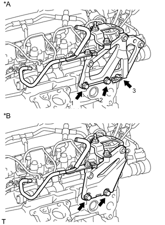
Text in Illustration *A 3-Bolt Type *B 2-Bolt Type
-
3-Bolt Type:
-
Temporarily install the No. 1 EGR cooler bracket with the 3 bolts in the sequence shown in the illustration.
-
Temporarily tighten bolt 1 and bolt 2.
- Torque:
- 10 N*m { 102 kgf*cm, 7 ft.*lbf }
-
Fully tighten bolt 3.
- Torque:
- 50 N*m { 510 kgf*cm, 37 ft.*lbf }
-
Fully tighten bolt 1 and bolt 2.
- Torque:
- 23 N*m { 235 kgf*cm, 17 ft.*lbf }
-
-
2-Bolt Type:
-
Install the No. 1 EGR cooler bracket with the 2 bolts
- Torque:
- 23 N*m { 235 kgf*cm, 17 ft.*lbf }
-
-
-
INSTALL EGR WITH COOLER PIPE ASSEMBLY
-
Install 2 new gaskets.
-
Install the EGR with cooler pipe assembly with the 4 bolts and 2 nuts.
- Torque:
- 23 N*m { 235 kgf*cm, 17 ft.*lbf }
-
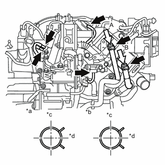
Text in Illustration *a View A *b View B *c Rear *d LH Connect the No. 2 water by-pass hose.
-
Connect the No. 2 oil cooler hose.
-
Connect the 3 vacuum transmitting hoses and vacuum hose.
-
-
INSTALL GENERATOR BRACKET
-
Install the generator bracket with the 2 bolts.
- Torque:
- 40 N*m { 407 kgf*cm, 30 ft.*lbf }
-
-
INSTALL GENERATOR ASSEMBLY
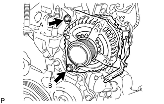
-
Install the generator with the 2 bolts.
- Torque:
- Bolt A
- 21 N*m { 214 kgf*cm, 15 ft.*lbf }
- Bolt B
- 54 N*m { 551 kgf*cm, 40 ft.*lbf }
-
-
INSTALL ENGINE COVER BRACKET
-
Install the engine cover bracket with the bolt.
- Torque:
- 21 N*m { 214 kgf*cm, 15 ft.*lbf }
-