ENGINE ASSEMBLY INSTALLATION

CAUTION / NOTICE / HINT
Note
-
As the engine assembly with transaxle is extremely heavy, the engine lifter may suddenly drop if the instructions listed in the repair manual are not followed. Therefore, always follow the instructions listed in the repair manual when performing this procedure.
-
When the transaxle is removed, be sure to use a new clutch release with bearing cylinder and new installation bolts. Removal of the transaxle allows the compressed clutch release with bearing cylinder to return to its original position, and dust could damage the seal of the clutch release with bearing cylinder, possibly causing clutch fluid leaks.
-
After replacing the engine assembly, perform both "Injector Compensation" and "Pilot Quantity Learning Values Reset" functions using the intelligent tester Click here.
PROCEDURE
-
INSTALL NO. 1 CRANKSHAFT POSITION SENSOR PLATE
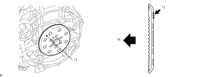
Text in Illustration *1 Mark "RR" - - *a Engine Block Side - -
-
Install the No. 1 crankshaft position sensor plate.
Note
Install the plate with the concave surface facing the cylinder block, as shown in the illustration.
-
-
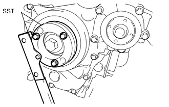
INSTALL FLYWHEEL SUB-ASSEMBLY
-
Hold the crankshaft with SST.
- SST
- 09213-58014
- 09330-00021
-
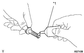
Text in Illustration *1 Adhesive Apply adhesive to the 2 or 3 end threads of the bolts.
Adhesive Toyota Genuine Adhesive 1324, Three Bond 1324 or equivalent. -
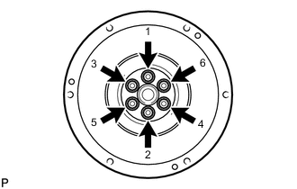
Using several steps, uniformly install and tighten the 6 bolts in the order shown in the illustration (Procedure "A").
- Torque:
- 49 N*m { 500 kgf*cm, 36 ft.*lbf }
-
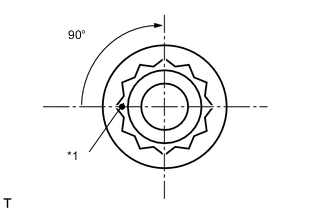
Text in Illustration *1 Paint Mark Mark the bolts with paint as shown in the illustration.
-
Retighten the bolts 90° in the same sequence as in procedure "A".
-
Check that the paint marks of each bolt are at a 90° angle from the original position.
-
-
INSTALL CRANKSHAFT POSITION SENSOR
-
Install the crankshaft position sensor with the 2 bolts.
- Torque:
- 7.0 N*m { 71 kgf*cm, 62 in.*lbf }
-
Engage the crankshaft position sensor wire harness clamp to the wire harness bracket.
-
Connect the crankshaft position sensor connector.
-
-
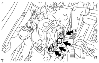
INSTALL ENGINE WIRE
-
Install the engine wire to the engine.
-
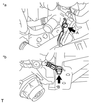
Text in Illustration *a Engine side *b Transaxle side Install the 2 ground bolts.
- Torque:
- Bolt A
- 8.4 N*m { 85 kgf*cm, 74 in.*lbf }
- Bolt B
- 13 N*m { 130 kgf*cm, 9 ft.*lbf }
-
-
INSTALL CYLINDER BLOCK SIDE COVER
-
Install the cylinder block side cover with the bolt and washer plate.
- Torque:
- 7.0 N*m { 71 kgf*cm, 62 in.*lbf }
-
-
INSTALL EXHAUST MANIFOLD
-
INSTALL INLET TURBO OIL PIPE SUB-ASSEMBLY
-
INSTALL TURBOCHARGER SUB-ASSEMBLY
-
INSTALL NO. 2 MANIFOLD SUPPORT BRACKET
-
Install the No. 2 manifold support bracket with the 2 bolts.
- Torque:
- 37 N*m { 377 kgf*cm, 27 ft.*lbf }
-
-
INSTALL MANIFOLD SUPPORT BRACKET
-
Install the manifold support bracket with the 3 bolts.
- Torque:
- 37 N*m { 377 kgf*cm, 27 ft.*lbf }
-
-
INSTALL EXHAUST MANIFOLD CONVERTER SUB-ASSEMBLY
-
Temporarily install the exhaust manifold converter sub-assembly with 3 new nuts and bolt.
-
Fully tighten the 3 new nuts first, and then tighten the bolt.
- Torque:
- Nut
- 26 N*m { 265 kgf*cm, 19 ft.*lbf }
- Bolt
- 37 N*m { 377 kgf*cm, 27 ft.*lbf }
-
Engage the 2 harness clamps to the harness bracket.
-
Engage the 2 harness clamps to the No. 2 timing chain cover.
-
Connect the 2 exhaust gas temperature sensor connectors.
-
-
INSTALL NO. 1 TURBO INSULATOR
-
Install the No. 1 turbo insulator with the 3 bolts.
- Torque:
- 7.0 N*m { 71 kgf*cm, 62 in.*lbf }
-
-
INSTALL DIFFERENTIAL PRESSURE SENSOR
-
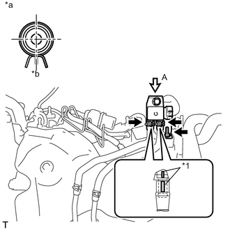
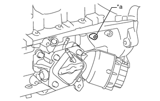
Text in Illustration *1 Paint Mark *a View A *b Rear Side Install the differential pressure sensor with the nut.
- Torque:
- 8.0 N*m { 82 kgf*cm, 71 in.*lbf }
-
Connect the 2 vacuum transmitting hoses.
-
Connect the differential pressure sensor connector.
-
-
INSTALL NO. 2 ENGINE COVER BRACKET
-
INSTALL CLUTCH DISC ASSEMBLY (for Manual Transaxle)
-
INSTALL CLUTCH DISC ASSEMBLY (for Multi-Mode Manual Transaxle)
(See page CLUTCH > CLUTCH UNIT (for EC65A) > INSTALLATION > INSTALL CLUTCH DISC ASSEMBLY)
-
INSTALL CLUTCH COVER ASSEMBLY (for Manual Transaxle)
-
INSTALL CLUTCH COVER ASSEMBLY (for Multi-Mode Manual Transaxle)
(See page CLUTCH > CLUTCH UNIT (for EC65A) > INSTALLATION > INSTALL CLUTCH COVER ASSEMBLY)
-
INSPECT AND ADJUST CLUTCH COVER ASSEMBLY (for Manual Transaxle)
-
INSPECT AND ADJUST CLUTCH COVER ASSEMBLY (for Multi-Mode Manual Transaxle)
(See page CLUTCH > CLUTCH UNIT (for EC65A) > INSTALLATION > INSPECT AND ADJUST CLUTCH COVER ASSEMBLY)
-
INSTALL CLUTCH RELEASE WITH BEARING CYLINDER ASSEMBLY (for Manual Transaxle)
-
INSTALL CLUTCH RELEASE WITH BEARING CYLINDER ASSEMBLY (for Multi-Mode Manual Transaxle)
(See page CLUTCH > CLUTCH UNIT (for EC65A) > INSTALLATION > INSTALL CLUTCH RELEASE WITH BEARING CYLINDER ASSEMBLY)
-
INSTALL BLEEDER CLUTCH RELEASE TUBE (for Manual Transaxle)
-
INSTALL BLEEDER CLUTCH RELEASE TUBE (for Multi-Mode Manual Transaxle)
(See page CLUTCH > CLUTCH UNIT (for EC65A) > INSTALLATION > INSTALL BLEEDER CLUTCH RELEASE TUBE)
-
INSPECT CLUTCH PIPE LINE (for Manual Transaxle)
-
INSPECT CLUTCH PIPE LINE (for Multi-Mode Manual Transaxle)
(See page CLUTCH > CLUTCH UNIT (for EC65A) > INSTALLATION > INSPECT CLUTCH PIPE LINE)
-
INSTALL CLUTCH RELEASE BLEEDER SUB-ASSEMBLY (for Manual Transaxle)
-
INSTALL CLUTCH RELEASE BLEEDER SUB-ASSEMBLY (for Multi-Mode Manual Transaxle)
(See page CLUTCH > CLUTCH UNIT (for EC65A) >INSTALLATION > INSTALL CLUTCH RELEASE BLEEDER SUB-ASSEMBLY)
-
INSTALL BLEEDER TO ACCUMULATOR TUBE (for Manual Transaxle)
-
INSTALL BLEEDER CLUTCH RELEASE TUBE (for Multi-Mode Manual Transaxle)
(See page CLUTCH > CLUTCH UNIT (for EC65A) > INSTALLATION > INSTALL BLEEDER CLUTCH RELEASE TUBE)
-
INSTALL MANUAL TRANSAXLE ASSEMBLY (for Manual Transaxle)
-
INSTALL CLUTCH ACTUATOR ASSEMBLY
(See page CLUTCH > CLUTCH ACTUATOR (for EC65A) > INSTALLATION
-
INSTALL MANUAL TRANSAXLE ASSEMBLY (for Multi-Mode Manual Transaxle)
(See page MULTI-MODE MANUAL TRANSAXLE (EC65A) > MULTI-MODE MANUAL TRANSAXLE ASSEMBLY > INSTALATION > INSTALL MANUAL TRANSAXLE ASSEMBLY)
-
INSTALL NO. 2 EXHAUST MANIFOLD CONVERTER SUB-ASSEMBLY
-
INSTALL NO. 3 MANIFOLD SUPPORT BRACKET
-
INSTALL NO. 4 MANIFOLD SUPPORT BRACKET
-
INSTALL DRIVE SHAFT HEAT INSULATOR SUB-ASSEMBLY
-
INSTALL NO. 2 VACUUM PIPE
-
INSTALL STARTER ASSEMBLY (for 1.6 kW Type)
-
INSTALL STARTER ASSEMBLY (for 2.0 kW Type)
(See page STARTING (1ND-TV) > STARTER (for 2.0 kw Type) > INSTALLATION > INSTALL STARTER ASSEMBLY)
-
INSTALL COMPRESSOR ASSEMBLY WITH PULLEY (w/ Air Conditioning System)
-
INSTALL NO. 2 AIR TUBE
-
Install the No. 2 air tube to the diesel throttle body assembly.
-
Text in Illustration *a Low height boss Install the No. 2 air tube assembly with bolt.
- Torque:
- 11 N*m { 112 kgf*cm, 8 ft.*lbf }
Note
Be sure to use the boss with low height to install the No.2 air tube.
-
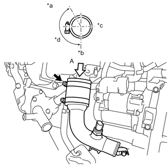
Text in Illustration *a View A *b Front Side *c LH Side *d Clamp installation range Tighten the hose clamps.
- Torque:
- 6.0 N*m { 61 kgf*cm, 53 in.*lbf }
Tech Tips
Check the torque in an hour after tightening and confirm that it is 1.8 N*m or higher.
-
-
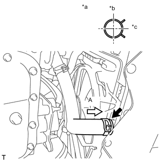
INSTALL NO. 2 RADIATOR HOSE
-
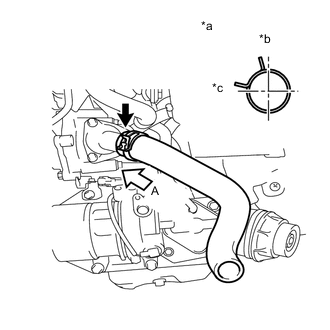
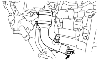
Text in Illustration *a View A *b Upper Side *c RH Side Install the No. 2 radiator hose.
-
-
INSTALL NO. 6 WATER BY-PASS HOSE
-
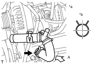
Text in Illustration *a View A *b Upper Side Install the No. 6 water by-pass hose.
-
-
TEMPORARILY TIGHTEN ENGINE MOUNTING INSULATOR SUB-ASSEMBLY RH
Tech Tips
Only perform this procedure when replacement of the engine mounting insulator RH is necessary.
-
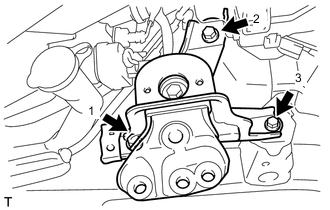
Install the engine mounting insulator RH with the 3 bolts, in the order shown in the illustration.
- Torque:
- 45 N*m { 459 kgf*cm, 33 ft.*lbf }
-
Install the relay block with the bolt.
- Torque:
- 5.4 N*m { 55 kgf*cm, 48 in.*lbf }
-
-
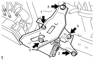
INSTALL ENGINE MOUNTING INSULATOR LH
Tech Tips
Only perform this procedure when replacement of the engine mounting insulator LH is necessary.
-
Temporarily tighten the engine mounting insulator with the 5 bolts.
-
Fully tighten the 5 bolts, in the order shown in the illustration.
- Torque:
- 52 N*m { 530 kgf*cm, 38 ft.*lbf }
-
-
INSTALL FRONT SUSPENSION CROSSMEMBER SUB-ASSEMBLY
-
Install the engine moving control rod with the through bolt.
- Torque:
- 120 N*m { 1224 kgf*cm, 89 ft.*lbf }
-
Remove the 2 bolts and the 2 engine hangers.
-
-
INSTALL ENGINE ASSEMBLY WITH TRANSAXLE
-
Place wooden blocks or plate lift attachments on an engine lifter, and then set the engine assembly with transaxle.
Note
-
Place the wooden blocks or plate lift attachments so that the front suspension crossmember sub-assembly is level.
-
As the front suspension crossmember subassembly is very heavy, be sure to support it securely.
-
-
Operate the engine lifter and lift the engine assembly with transaxle and the front suspension crossmember to the position where the engine mounting insulators RH and LH can be installed.
-
Install the engine mounting insulator LH with the through bolt and nut.
- Torque:
- 52 N*m { 530 kgf*cm, 38 ft.*lbf }
Tech Tips
Tighten by holding the nut and turning the bolt.
-
Install the engine mounting insulator RH with the bolt and 3 nuts.
- Torque:
- Bolt
- 88 N*m { 897 kgf*cm, 65 ft.*lbf }
- Nut A
- 52 N*m { 530 kgf*cm, 38 ft.*lbf }
- Nut B
- 88 N*m { 897 kgf*cm, 65 ft.*lbf }
-
Install the engine mounting stay with the 2 bolts.
- Torque:
- 88 N*m { 897 kgf*cm, 65 ft.*lbf }
-
By inserting SST into the datum holes in the front suspension crossmembers RH and LH alternately, tighten bolts A, B and C on both sides to the specified torque, in several steps.
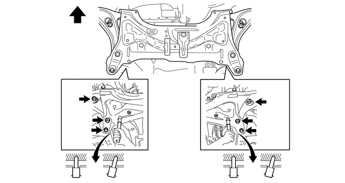
Text in Illustration *a Datum Hole - - 
Front of the Vehicle - - - SST
- 09670-00010
- Torque:
- Bolt A
- 87 N*m { 887 kgf*cm, 64 ft.*lbf }
- Bolt B
- 151 N*m { 1540 kgf*cm, 111 ft.*lbf }
- Bolt C
- 98 N*m { 999 kgf*cm, 72 ft.*lbf }
Note
-
Insert SST into the datum hole vertically.
-
If impossible to insert SST vertically, loosen all bolts and then insert SST again.
-
-
INSTALL OIL PAN COVER
-
INSTALL FRONT DRIVE SHAFT ASSEMBLY LH
-
INSTALL FRONT EXHAUST PIPE ASSEMBLY
-
INSTALL FRONT FLOOR CENTER BRACE
-
INSTALL NO. 1 STEERING COLUMN HOLE COVER SUB-ASSEMBLY
-
INSTALL STEERING SLIDING YOKE SUB-ASSEMBLY
-
INSTALL COLUMN HOLE COVER SILENCER SHEET
-
CONNECT TRANSAXLE WIRE (for Multi-Mode Manual Transaxle)
-
Connect the 5 connectors and 3 clamps.
-
-
CONNECT ENGINE WIRE
-
Connect the 2 connectors and the clamp to the engine room junction block.
-
Install the engine room junction block cover.
-
Connect the engine wire harness connector to the ECM.
-
Engage the wire harness clamp.
-
Install the engine earth bolt.
- Torque:
- 8.4 N*m { 85 kgf*cm, 74 in.*lbf }
-
Connect the current sensor connector and glow relay connector.
-
Connect the 3 connectors to the battery terminal.
-
-
INSTALL CLUTCH HOSE
-
CONNECT TRANSMISSION CONTROL CABLE ASSEMBLY (for Manual Transaxle)
-
INSTALL AIR PIPE SUB-ASSEMBLY
Text in Illustration *a View A *b LH Side *c Rear Side *d Clamp installation range
-
Insert the No. 1 air hose to the turbo charger sub-assembly.
-
Install the air pipe sub-assembly with the 2 nuts.
- Torque:
- 20 N*m { 199 kgf*cm, 14 ft.*lbf }
-
Tighten the hose clamp.
- Torque:
- 6.0 N*m { 61 kgf*cm, 53 in.*lbf }
-
Connect the wire harness with the bolt.
- Torque:
- 8.4 N*m { 85 kgf*cm, 74 in.*lbf }
-
-
INSTALL NO. 3 AIR HOSE
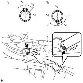
Text in Illustration *a View A *b View B *c Upper Side *d Rear Side *e Clamp installation range
-
Install the No. 3 air hose with the 2 hose clamps.
- Torque:
- 6.0 N*m { 61 kgf*cm, 53 in.*lbf }
-
-
CONNECT NO. 2 RADIATOR HOSE
-
Text in Illustration *a View A *b Upper Side *c LH Side Connect the No. 2 radiator hose.
-
-
INSTALL NO. 1 RADIATOR HOSE
-
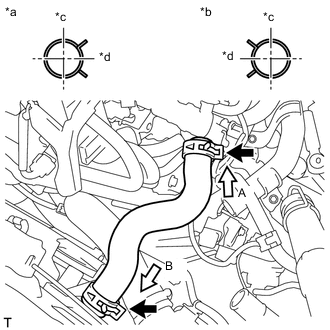
Text in Illustration *a View A *b View B *c Upper Side *d LH Side Install the No. 1 radiator hose.
-
-
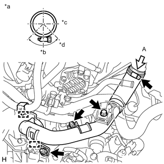
INSTALL NO. 2 AIR HOSE
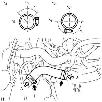
Text in Illustration *a View A *b View B *c Upper Side *d Front Side *e LH Side *f Clamp installation range
-
Install the No. 2 air hose with the 2 hose clamps.
- Torque:
- 6.0 N*m { 61 kgf*cm, 53 in.*lbf }
-
-
CONNECT INLET HEATER WATER HOSE
-
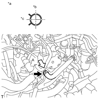
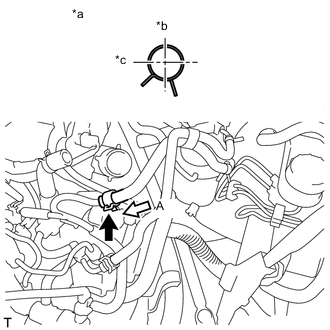
Text in Illustration *a View A *b Upper Side *c Rear Side Connect the inlet heater water hose.
-
-
CONNECT OUTLET HEATER WATER HOSE
-
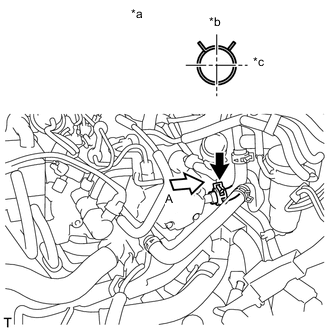
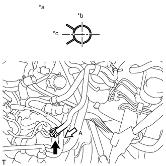
Text in Illustration *a View A *b Upper Side *c RH Side Connect the outlet heater water hose.
-
-
CONNECT NO. 1 FUEL HOSE
-
Text in Illustration *a View A *b Upper Side *c Front Side Connect the No. 1 fuel hose to the supply pump.
-
-
CONNECT NO. 2 FUEL HOSE
-
Text in Illustration *a View A *b Upper Side *c Front Side Connect the No. 2 fuel hose to the supply pump.
-
-
CONNECT UNION TO CONNECTOR TUBE HOSE
-
Text in Illustration *a View A *b Upper Side *c Front Side Connect the union to connector tube hose.
-
-
CONNECT NO. 1 COOLER REFRIGERANT DISCHARGE HOSE (w/ Air Conditioning System)
-
CONNECT SUCTION HOSE (w/ Air Conditioning System)
-
INSTALL FAN AND GENERATOR V BELT
-
INSPECT FAN AND GENERATOR V BELT
-
INSTALL BATTERY CARRIER
-
Install the battery carrier with the 5 bolts.
- Torque:
- 17 N*m { 173 kgf*cm, 13 ft.*lbf }
-
Engage the 3 clamps and connect the wire harness onto the battery carrier.
-
-
INSTALL BATTERY TRAY
-
Install the battery tray onto the battery carrier.
-
-
INSTALL BATTERY
-
Install the battery onto the battery tray.
-
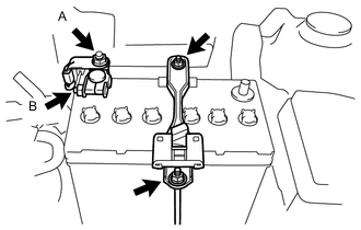
Install the battery clamp sub-assembly with the 2 nuts.
- Torque:
- 3.5 N*m { 36 kgf*cm, 31 in.*lbf }
-
Connect the cable to the positive (+) battery terminal with the bolt B.
- Torque:
- 5.4 N*m { 55 kgf*cm, 48 in.*lbf }
-
Connect the engine wire with the bolt A.
- Torque:
- 7.6 N*m { 77 kgf*cm, 66 in.*lbf }
-
-
INSTALL AIR CLEANER BRACKET
-
Install the air cleaner No. 1 bracket with the 3 bolts.
- Torque:
- 20 N*m { 199 kgf*cm, 14 ft.*lbf }
-
-
CONNECT CABLE TO NEGATIVE BATTERY TERMINAL
- Torque:
- 5.4 N*m { 55 kgf*cm, 48 in.*lbf }
-
FILL CLUTCH ACTUATOR RESERVOIR WITH BRAKE FLUID (for Multi-Mode Manual Transaxle)
(See page CLUTCH > CLUTCH SYSTEM (for EC65A) > BLEEDING > FILL CLUTCH ACTUATOR RESERVOIR WITH BRAKE FRUID)
-
BLEED CLUTCH LINE
(See page CLUTCH > CLUTCH ACTUATOR (for EC65A) > INSTALLATION > BLEED CLUTCH LINE)
-
INSTALL AIR CLEANER CASE SUB-ASSEMBLY WITH INLET AIR CLEANER
-
Install the air cleaner case sub-assembly with inlet air cleaner with the 3 bolts.
- Torque:
- 7.8 N*m { 80 kgf*cm, 69 in.*lbf }
-
-
INSTALL AIR CLEANER FILTER ELEMENT SUB-ASSEMBLY
-
INSTALL AIR CLEANER CAP SUB-ASSEMBLY WITH HOSE
-
INSTALL RADIATOR RESERVE TANK BRACKET
-
Install the radiator reserve tank bracket with the bolt.
- Torque:
- 20 N*m { 199 kgf*cm, 14 ft.*lbf }
-
-
INSTALL RADIATOR RESERVE TANK ASSEMBLY
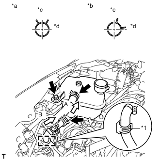
Text in Illustration *1 Paint Mark *a View A *b View B *c Upper Side *d Rear Side
-
Install the radiator reserve tank with the bolt.
- Torque:
- 13 N*m { 127 kgf*cm, 9 ft.*lbf }
-
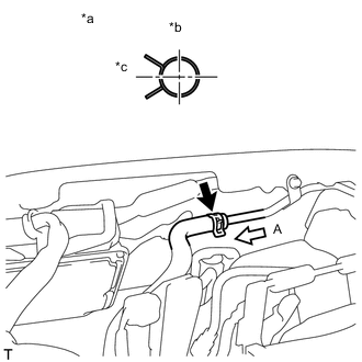
Engage the hose clamp and connect the No. 5 water by-pass hose.
Note
Align the No. 5 water by-pass hose paint mark with the clamp center.
-
Connect the No. 4 water by-pass hose.
-
-
INSTALL OUTER COWL TOP PANEL
-
Install the outer cowl top panel with the 6 bolts.
- Torque:
- 7.0 N*m { 71 kgf*cm, 62 in.*lbf }
-
Engage the 2 wire harness clamps.
-
-
INSTALL INNER COWL TOP TO COWL BRACE
-
Install the inner cowl top to cowl brace with the 2 bolts.
- Torque:
- 7.0 N*m { 71 kgf*cm, 62 in.*lbf }
-
-
INSTALL COWL TOP INSIDE CORNER PANEL LH
-
INSTALL INNER COWL TOP REINFORCEMENT
-
INSTALL FRONT NO. 1 VENTILATOR SEAL
-
Engage the clamp and install the front No. 1 ventilator seal.
-
-
INSTALL FRONT AIR SHUTTER SEAL RH
Tech Tips
Use the same procedures for the front No. 1 ventilator seal.
-
INSTALL FRONT WIPER MOTOR AND LINK
-
ADD TRANSAXLE OIL (for Manual Transaxle)
-
ADD TRANSAXLE OIL (for Multi-Mode Manual Transaxle)
(See page MULTI-MODE MANUAL TRANSAXLE (EC65A) > MULTI-MODE MANUAL TRANSAXLE OIL > REPLACEMENT > ADD MANUAL TRANSAXLE OIL)
-
FILL RESERVOIR WITH BRAKE FLUID
-
INSPECT FLUID LEVEL
-
ADD ENGINE OIL
-
ADD ENGINE COOLANT
-
BLEED AIR FROM FUEL SYSTEM
-
INITIALIZATION AND REGISTRATION
-
INITIALIZATION OF MULTI-MODE MANUAL TRANSAXLE ECU (for Multi-Mode Manual Transaxle)
(See page MULTI-MODE MANUAL TRANSAXLE (EC65A) > MULTI-MODE MANUAL TRANSAXLE ECU > INSTALLATION > PERFORM INITIALIZATION OF TCM)
-
LEARNING OF MULTI-MODE MANUAL TRANSAXLE SYSTEM (for Multi-Mode Manual Transaxle)
(See page MULTI-MODE MANUAL TRANSAXLE (EC65A) > MULTI-MODE MANUAL TRANSAXLE ECU > INSTALLATION > PERFORM LEARNING OF MULTI-MODE MANUAL TRANSMISSION)
-
SYNCHRONIZATION POSITION CALIBRATION (for Multi-Mode Manual Transaxle)
(See page MULTI-MODE MANUAL TRANSAXLE (EC65A) > MULTI-MODE MANUAL TRANSAXLE ECU > INSTALLATION > PERFORM SYNCHRONIZATION POSITION CALIBRATION)
-
CHARGE REFRIGERANT (w/ Air Conditioning System)
-
INSPECT MANUAL TRANSAXLE OIL (for Manual Transaxle)
-
INSPECT MANUAL TRANSAXLE OIL (for Multi-Mode Manual Transaxle)
(See page MULTI-MODE MANUAL TRANSAXLE (EC65A) > MULTI-MODE MANUAL TRANSAXLE OIL > ON-VEHICLE INSPECTION > INSPECT MANUAL TRANSAXLE OIL)
-
CHECK ENGINE OIL LEVEL
-
INSPECT FOR OIL LEAK
-
INSPECT FOR COOLANT LEAK
-
CHECK FUEL LEAK
-
INSPECT FOR EXHAUST GAS LEAK
-
WARM UP ENGINE (w/ Air Conditioning System)
-
INSPECT FOR REFRIGERANT LEAK (w/ Air Conditioning System)
-
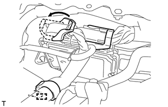
INSTALL NO. 1 ENGINE COVER
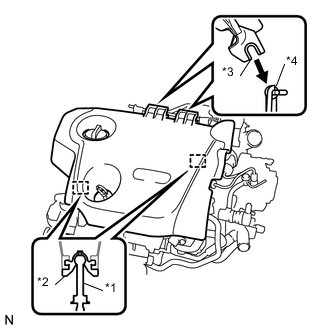
Text in Illustration *1 Pin *2 Grommet *3 Hook *4 Bracket
-
Attach the No. 1 engine cover hooks to the bracket. Then align the No. 1 engine cover grommets with the 2 pins, and press down on the No. 1 engine cover to attach the pins.
-
-
INSTALL ENGINE UNDER COVER RH
-
Install the engine under cover RH with the 2 bolts.
- Torque:
- 5.0 N*m { 51 kgf*cm, 44 in.*lbf }
-
-
INSTALL ENGINE UNDER COVER LH
Tech Tips
Use the same procedures for the LH and RH side.
-
INSTALL CENTER ENGINE UNDER COVER
-
Install the center engine under cover with the 9 screws and 5 clips.
-
Install the bolts.
- Torque:
- 5.0 N*m { 51 kgf*cm, 44 in.*lbf }
-
-
INSTALL FRONT WHEELS
- Torque:
- 103 N*m { 1050 kgf*cm, 76 ft.*lbf }
-
INSPECT AND ADJUST FRONT WHEEL ALIGNMENT
-
CHECK SPEED SENSOR SIGNAL (w/o VSC)
-
CHECK SPEED SENSOR SIGNAL (w/ VSC)