ENGINE ASSEMBLY REMOVAL

CAUTION / NOTICE / HINT
Note
As the engine assembly with transaxle is extremely heavy, the engine lifter may suddenly drop if the instructions listed in the repair manual are not followed. Therefore, always follow the instructions listed in the repair manual when performing this procedure.
PROCEDURE
-
DISCHARGE FUEL SYSTEM PRESSURE
-
PRECAUTION
Note
After turning the ignition switch off, waiting time may be required before disconnecting the cable from the battery terminal. Therefore, make sure to read the disconnecting the cable from the battery terminal notice before proceeding with work Click here.
-
DISCONNECT CABLE FROM NEGATIVE BATTERY TERMINAL
Note
When disconnecting the cable, some systems need to be initialized after the cable is reconnected Click here.
-
DRAIN ENGINE COOLANT
-
DRAIN CONTINUOUSLY VARIABLE TRANSAXLE FLUID (for CVT)
(See page MULTIDRIVE / CVT (K310) > OIL PAN > REMOVAL > DRAIN CONTINUOUSLY VARIABLE TRANSAXLE FRUID)
-
DRAIN MANUAL TRANSAXLE OIL (for Manual Transaxle)
-
REMOVE FRONT WHEELS
-
REMOVE ENGINE UNDER COVER LH
-
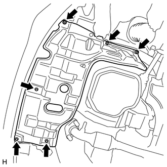
Remove the 3 screws and the 3 bolts.
-
Remove the engine under cover LH.
-
-
REMOVE ENGINE UNDER COVER RH
-
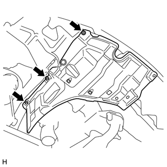
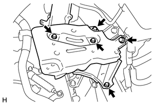
Remove the screw and the 2 bolts.
-
Remove the engine under cover RH.
-
-
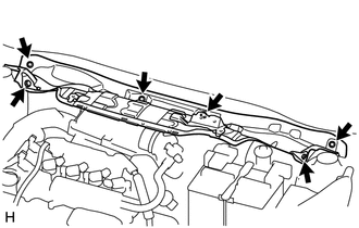
REMOVE WINDSHIELD WIPER LINK ASSEMBLY
-
REMOVE FRONT NO. 1 VENTILATOR SEAL
-
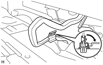
Disengage the clip and remove the front No. 1 ventilator seal.
-
-
REMOVE FRONT AIR SHUTTER SEAL RH
Tech Tips
Use the same procedure for the front No. 1 ventilator seal.
-
REMOVE COWL TOP INSIDE CORNER PANEL LH (for LHD)
-
REMOVE COWL TOP INSIDE CORNER PANEL RH (for RHD)
-
REMOVE INNER COWL TOP REINFORCEMENT (for LHD)
-
REMOVE INNER LOWER COWL TOP REINFORCEMENT (for RHD)
-
REMOVE INNER COWL TOP TO COWL BRACE (for LHD)
-
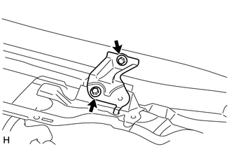
Remove the 2 bolts and the inner cowl top to cowl brace.
-
-
REMOVE INNER COWL TOP TO COWL BRACE (for RHD)
Tech Tips
Use the same procedure for the RH and LH sides.
-
REMOVE OUTER COWL TOP PANEL (for LHD)
-
Remove the 6 bolts and the outer cowl top panel.
-
-
REMOVE OUTER COWL TOP PANEL (for RHD)
Tech Tips
Use the same procedure for the RH and LH sides.
-
REMOVE FAN AND GENERATOR V BELT
-
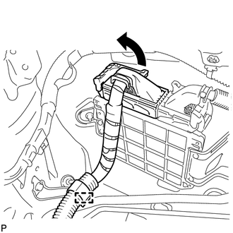
REMOVE BATTERY
-
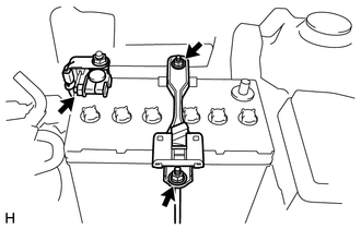
Disconnect the cable from the positive (+) battery terminal.
-
Loosen the 2 nuts, and remove the battery carrier clamp.
-
Remove the battery.
-
-
REMOVE BATTERY TRAY
-
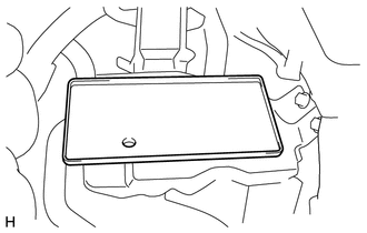
Remove the battery tray.
-
-
REMOVE BATTERY CARRIER
-
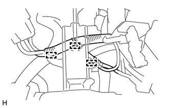
Disengage the 3 clamps and disconnect the wire harness from the battery carrier.
-
Remove the 5 bolts and the battery carrier.
-
-
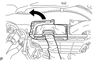
REMOVE NO. 1 ENGINE COVER
-
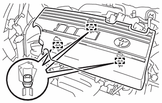
Disengage the 3 clamps and remove the No. 1 engine cover.
-
-
REMOVE INLET NO. 1 AIR CLEANER
-
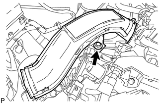
Remove the bolt and the inlet No. 1 air cleaner.
-
-
REMOVE AIR CLEANER AND HOSE ASSEMBLY
-
Disengage the clamp and disconnect the intake mass air flow meter connector.
-
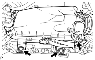
Remove the 2 bolts and separate the air cleaner and hose assembly.
-
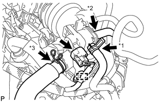
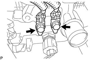
Text in Illustration *1 No. 1 fuel vapor feed hose *2 No. 2 fuel vapor feed hose *3 No. 2 ventilation hose Disengage the clamp and disconnect the No. 1 vacuum switching valve assembly connector.
-
Disconnect the No. 1 fuel vapor feed hose and the No. 2 fuel vapor feed hose from the No. 1 vacuum switching valve assembly.
-
Disconnect the No. 2 ventilation hose from the air cleaner hose.
-
Using pliers, grip the claws of the clip and remove the air cleaner and hose assembly.
-
-
DISCONNECT UNION TO CONNECTOR TUBE HOSE
-
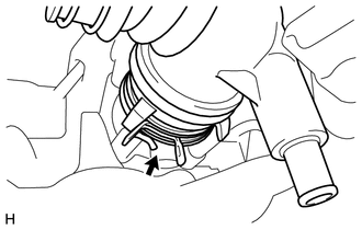
Disengage the hose clamp.
-
Loosen the clip and remove the union to connector tube hose.
-
-
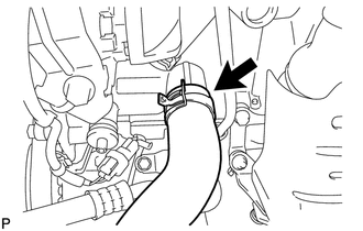
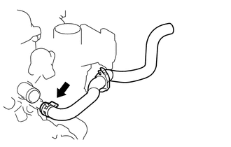
DISCONNECT NO. 1 RADIATOR HOSE
-
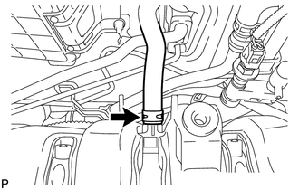
Disengage the hose clamp.
-
Loosen the clip and remove the No. 1 radiator hose.
-
-
DISCONNECT NO. 2 RADIATOR HOSE
-
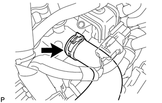
Disengage the hose clamp.
-
Loosen the clip and remove the No. 2 radiator hose.
-
-
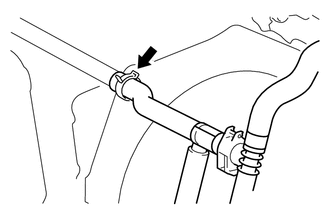
SEPARATE INLET HEATER WATER HOSE A
-
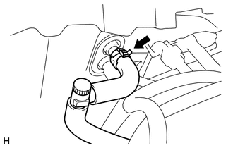
Disengage the hose clamp.
-
Loosen the clip and remove the inlet heater water hose A.
-
-
SEPARATE WATER HOSE SUB-ASSEMBLY B
-
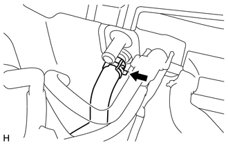
Disengage the hose clamp.
-
Loosen the clip and remove the water hose sub-assembly B.
-
-
REMOVE EFI FUEL PIPE CLAMP
-
DISCONNECT FUEL TUBE SUB-ASSEMBLY
-
SEPARATE TRANSMISSION CONTROL CABLE ASSEMBLY (for CVT)
(See page MULTIDRIVE / CVT (K310) > TRANSMISSION CONTROL ABLE > REMOVAL > REMOVE TRANSMISSION CONTROL CABLE ASSEMBLY)
-
SEPARATE TRANSMISSION CONTROL CABLE ASSEMBLY (for Manual Transaxle)
-
SEPARATE CLUTCH HOSE (for Manual Transaxle)
-
SEPARATE COMPRESSOR ASSEMBLY WITH PULLEY (w/ Air Conditioning System)
-
Disconnect the connector.
-
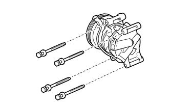
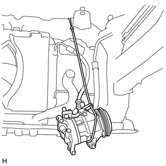
Remove the 4 bolts and the separate the compressor assembly with pulley.
Tech Tips
It is not necessary to completely remove the compressor. With the hoses connected to the compressor, hang the compressor on the vehicle body with a rope.
-
-
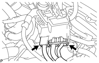
DISCONNECT ECM CONNECTOR (for LHD)
-
Pull up the lever and disconnect the ECM connector.
-
Disengage the clamp and disconnect the engine wire.
-
-
DISCONNECT ECM CONNECTOR (for RHD)
-
Pull up the lever and disconnect the ECM connector.
-
-
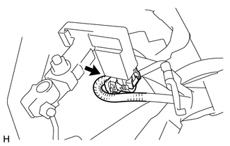
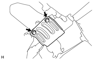
DISCONNECT ENGINE WIRE
-
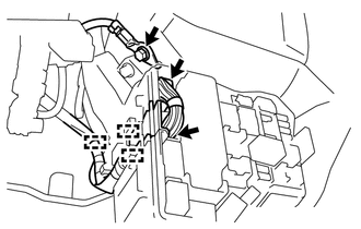
Remove the engine room relay block cover.
-
Disengage the 3 clamps and disconnect the 2 connectors, and then disconnect the engine wire from the engine room relay block.
-
Remove the bolt and separate the ground wire.
-
Disconnect the 2 connectors from the positive battery terminal.
-
Disconnect the connector from the negative battery terminal.
-
Check that the engine wire is disconnected between the body and engine assembly with transaxle.
-
-
REMOVE COLUMN HOLE COVER SILENCER SHEET
-
SEPARATE STEERING SLIDING YOKE SUB-ASSEMBLY
-
REMOVE NO. 1 STEERING COLUMN HOLE COVER SUB-ASSEMBLY
-
REMOVE DRIVE SHAFT HEAT INSULATOR SUB-ASSEMBLY
-
Remove the 2 bolts and remove the drive shaft heat insulator sub-assembly.
-
-
REMOVE FRONT DRIVE SHAFT ASSEMBLY
-
REMOVE FRONT FLOOR CENTER BRACE
-
REMOVE FRONT EXHAUST PIPE ASSEMBLY
-
REMOVE FLYWHEEL HOUSING SIDE COVER
-
REMOVE STARTER ASSEMBLY (w/ Stop And Start System)
-
REMOVE STARTER ASSEMBLY (w/o Stop And Start System)
-
REMOVE DRIVE PLATE AND TORQUE CONVERTER CLUTCH SETTING BOLT (for CVT)
-
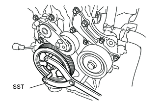
Use SST to hold the crankshaft pulley in place.
- SST
- 09960-10010 ( 09962-01000, 09963-01000 )
-
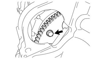
Remove the 6 drive plate and torque converter setting bolts.
-
-
REMOVE ENGINE ASSEMBLY WITH TRANSAXLE
-
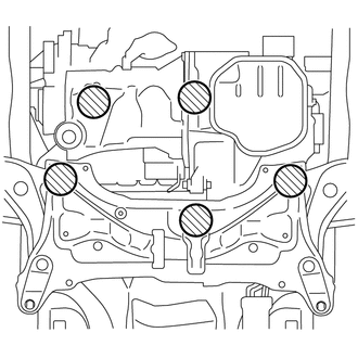
Place wooden blocks or plate lift attachments in the positions shown in the illustration and set an engine lifter underneath the engine assembly with transaxle.
Text in Illustration 
Attachment Placement Positions Note
-
Place the wooden blocks or plate lift attachments so that the engine assembly with transaxle is level.
-
As the engine assembly with transaxle is very heavy, be sure to support it securely.
-
-
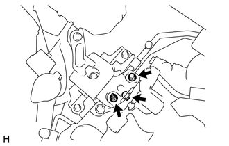
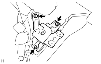
Remove the bolt and 2 nuts, and then separate the engine mounting insulator sub-assembly RH.
-
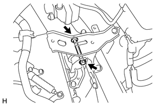
Remove the bolt and nut, and then separate the engine mounting insulator LH.
-
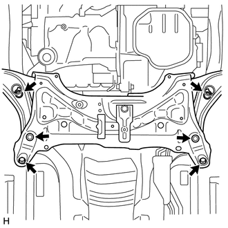
Remove the 6 bolts shown in the illustration.
-
Operate the engine lifter and slowly remove the engine from the vehicle.
Note
Make sure the engine is clear of all wiring and hoses.
-
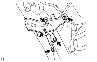
Remove the 3 bolts and the engine mounting insulator sub-assembly RH.
Tech Tips
Only perform this procedure when replacement of the engine mounting insulator sub-assembly RH is necessary.
-
Remove the 5 bolts and the engine mounting insulator LH.
Tech Tips
Only perform this procedure when replacement of the engine mounting insulator LH is necessary.
-
-
REMOVE CONTINUOUSLY VARIABLE TRANSAXLE ASSEMBLY (for CVT)
(See page MULTIDRIVE / CVT (K310) > CONTINUOSLY VARIABLE TRANSAXLE ASSEMBLY > REMOVAL)
-
REMOVE MANUAL TRANSAXLE ASSEMBLY (for Manual Transaxle)
-
INSTALL ENGINE HANGER
-

Text in Illustration *1 No. 1 Engine Hanger *2 No. 2 Engine Hanger Install the 2 engine hangers with the 2 bolts.
- Torque:
- 43 N*m { 438 kgf*cm, 31 ft.*lbf }
Tech Tips
Part Name Part No. No. 1 engine hanger 12281-47022 or 12281-47023 No. 2 engine hanger 12282-47010 Bolt 91552-81040 -
Attach the engine sling device to the engine hangers.
-
-
REMOVE GENERATOR ASSEMBLY
-
REMOVE ENGINE WIRE
-
Remove the 2 bolts and separate the 2 ground wires from the cylinder head.
-
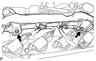
Remove the 2 nuts and separate the engine wire from the cylinder head cover.
-
Disconnect all of the clamps and connectors and remove the engine wire from the engine assembly.
-
-
REMOVE WATER HOSE SUB-ASSEMBLY B (for CVT)
-
Disengage the hose clamp.
-
Loosen the clip and remove the water hose sub-assembly B.
-
-
REMOVE WATER HOSE SUB-ASSEMBLY B (for Manual Transaxle)
Tech Tips
Use the same procedure for the water hose sub-assembly B.
-
REMOVE WATER BY-PASS HOSE ASSEMBLY (for CVT)
-
Disengage the hose clamp.
-
Loosen the clip and remove the water by-pass hose assembly.
-
-
REMOVE WATER HOSE SUB-ASSEMBLY (for Manual Transaxle)
Tech Tips
Use the same procedure for the water by-pass hose assembly.
-
REMOVE DRIVE PLATE AND RING GEAR SUB-ASSEMBLY (for CVT)
-
REMOVE CLUTCH COVER ASSEMBLY (for Manual Transaxle)
-
REMOVE CLUTCH DISC ASSEMBLY (for Manual Transaxle)
-
INSPECT FLYWHEEL SUB-ASSEMBLY (for Manual Transaxle)
-
REMOVE FLYWHEEL SUB-ASSEMBLY (for Manual Transaxle)
-
REMOVE FLYWHEEL SUB-ASSEMBLY (w/ Stop And Start System)
-
REMOVE INNER OIL SEAL (w/ Stop and Start System)
-
REMOVE ONE-WAY CLUTCH ASSEMBLY (w/ Stop and Start System)
-
INSPECT RING GEAR SUB-ASSEMBLY (w/ Stop and Start System)
-
REMOVE RING GEAR SUB-ASSEMBLY (w/ Stop and Start System)
-
INSPECT ONE-WAY CLUTCH ASSEMBLY (w/ Stop and Start System)
-
INSTALL ENGINE ON ENGINE STAND
-
Using a sling device and a chain block, install the engine on an engine stand.
-