CYLINDER HEAD GASKET INSTALLATION
PROCEDURE
-
INSTALL CYLINDER HEAD GASKET
-
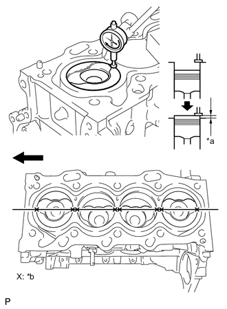
Inspect the protrusion height of the piston heads.
-
Place a dial indicator on the cylinder block as shown in the illustration.
Text in Illustration 
Engine Front *a Protrusion *b Measuring Point Note
Make sure that the dial indicator is at right angles to the cylinder block top surface.
-
Measure the protrusion height of the piston head of each cylinder at 2 places as shown in the illustration.
-
-
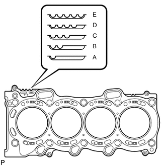
Select a new cylinder head gasket.
-
Select the highest protrusion height among the 8 measurements recorded. It is used to select a new cylinder head gasket.
Piston Protrusion Piston Protrusion mm (in.) Gasket Cutout Gasket Size 0.525 to 0.575
(0.020 to 0.023)
1 A 0.576 to 0.625
(0.023 to 0.025)
2 B 0.626 to 0.675
(0.025 to 0.027)
3 C 0.676 to 0.725
(0.027 to 0.029)
4 D 0.726 to 0.775
(0.029 to 0.031)
5 E
-
-
Install the cylinder head gasket.
-
Apply seal packing (Diameter 3.5 to 4.5 mm (0.138 to 0.177 in.)) to the cylinder block side as shown in the illustration.
Seal packing Toyota Genuine Seal Packing Black, Three Bond 1207B or equivalent Note
Remove any oil from the contact surface.
-
Place a new cylinder head gasket on the cylinder block with the Lot No. stamp facing upward.
-
Apply seal packing (Diameter 3.5 to 4.5 mm (0.138 to 0.177 in.)) to the top surface of the cylinder head again as shown in the illustration.
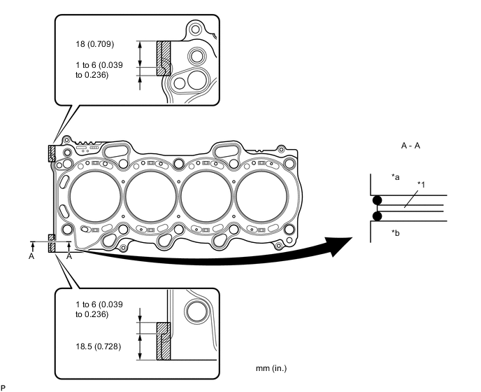
Text in Illustration *1 Cylinder Head Gasket - - *a Cylinder Head Side *b Cylinder Block Side Seal packing Toyota Genuine Seal Packing Black, Three Bond 1207B or equivalent -
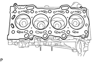
Install the cylinder head gasket onto the cylinder block.
Note
-
Remove any oil from the contact surface.
-
Install the cylinder head within 3 minutes, and tighten the bolts within 15 minutes of applying the seal packing.
-
-
-
-
INSTALL CYLINDER HEAD SUB-ASSEMBLY
-
CONNECT INLET WATER HOSE RH
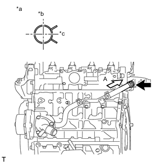
Text in Illustration *a View A *b Upper *c Rear
-
Connect the inlet water hose RH.
-
-
INSTALL NO. 1 VALVE ROCKER ARM SUB-ASSEMBLY
-
INSTALL CAMSHAFT
-
INSTALL CHAIN SUB-ASSEMBLY
-
INSTALL NO. 1 CHAIN VIBRATION DAMPER
-
INSTALL CHAIN TENSIONER SLIPPER
-
INSTALL NO. 1 CHAIN TENSIONER ASSEMBLY
-
REPLACE TIMING CHAIN COVER OIL SEAL
-
INSTALL TIMING CHAIN COVER SUB-ASSEMBLY
-
CONNECT INLET WATER HOSE LH
-
INSTALL CRANKSHAFT DAMPER SUB-ASSEMBLY
-
INSTALL NO. 2 TIMING CHAIN COVER
-
INSTALL ENGINE MOUNTING BRACKET RH
-
CHECK VALVE CLEARANCE
-
ADJUST VALVE CLEARANCE
-
INSTALL CYLINDER HEAD COVER SUB-ASSEMBLY
-
INSTALL HARNESS BRACKET
-
INSTALL V-RIBBED BELT TENSIONER ASSEMBLY
-
INSTALL VACUUM PUMP ASSEMBLY
-
INSTALL CAMSHAFT POSITION SENSOR
-
INSTALL WATER BY-PASS PIPE SUB-ASSEMBLY
-
INSTALL NO. 4 WATER BY-PASS HOSE
-
INSTALL NO. 2 OIL COOLER HOSE
-
INSTALL NO. 2 CYLINDER HEAD COVER
-
INSTALL NO. 1 INTAKE MANIFOLD INSULATOR
-
INSTALL COMMON RAIL ASSEMBLY
-
INSTALL SUPPLY PUMP DRIVE COUPLING
-
TEMPORARILY TIGHTEN SUPPLY PUMP ASSEMBLY
-
INSTALL FUEL INLET PIPE SUB-ASSEMBLY
-
INSTALL NO. 2 FUEL HOSE
-
INSTALL INJECTION NOZZLE SEAT
-
INSTALL INJECTOR ASSEMBLY
-
INSTALL NOZZLE HOLDER CLAMP SEAT
-
INSTALL NO. 1 NOZZLE HOLDER CLAMP
-
INSTALL NOZZLE LEAKAGE PIPE ASSEMBLY
-
INSTALL NOZZLE LEAKAGE PIPE SET CLAMP
-
INSTALL NO. 2 INTAKE MANIFOLD INSULATOR
-
INSTALL GLOW PLUG ASSEMBLY
-
INSTALL NO. 1 GLOW PLUG CONNECTOR
-
INSTALL NO. 1 INJECTION PIPE SUB-ASSEMBLY
-
INSTALL NO. 2 INJECTION PIPE SUB-ASSEMBLY
-
INSTALL NO. 3 INJECTION PIPE SUB-ASSEMBLY
-
INSTALL INTAKE AIR CONNECTOR WITH DIESEL THROTTLE BODY ASSEMBLY
-
INSTALL NO. 1 OIL HOSE
-
INSTALL OIL LEVEL DIPSTICK GUIDE SUB-ASSEMBLY
-
INSTALL ENGINE OIL LEVEL DIPSTICK
-
INSTALL ELECTRIC EGR CONTROL VALVE ASSEMBLY
-
INSTALL HARNESS BRACKET
-
INSTALL NO. 1 EGR COOLER BRACKET
-
INSTALL EGR WITH COOLER PIPE ASSEMBLY
-
INSTALL GENERATOR BRACKET
-
INSTALL GENERATOR ASSEMBLY
-
INSTALL ENGINE COVER BRACKET
-
INSTALL ENGINE ASSEMBLY