VALVE CLEARANCE ADJUSTMENT

PROCEDURE
-
PRECAUTION
Note
After turning the ignition switch off, waiting time may be required before disconnecting the cable from the battery terminal. Therefore, make sure to read the disconnecting the cable from the battery terminal notice before proceeding with work Click here.
-
DISCONNECT CABLE FROM NEGATIVE BATTERY TERMINAL
-
REMOVE CENTER ENGINE UNDER COVER
-
REMOVE ENGINE UNDER COVER RH
-
REMOVE NO. 1 ENGINE COVER
-
SEPARATE ENGINE WIRE
-
REMOVE VACUUM PUMP ASSEMBLY
-
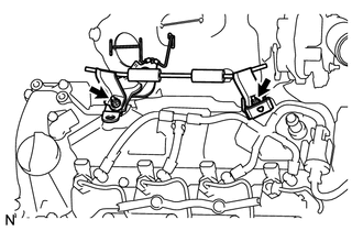
REMOVE NO. 2 ENGINE COVER BRACKET
-
Remove the 2 nuts and No. 2 engine cover bracket.
-
Remove the air fuel ratio sensor bracket and the harness bracket.
-
-
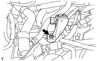
SEPARATE SENSOR BRACKET
-
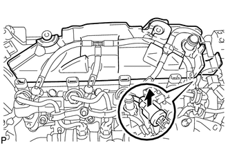
Remove the nut and separate the sensor bracket.
-
-
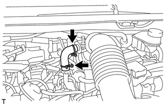
REMOVE VENTILATION HOSE
-
Remove the ventilation hose.
-
-
REMOVE NO. 2 CYLINDER HEAD COVER
-
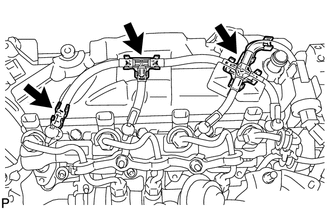
Remove the 3 nozzle leakage pipe set clamps.
-
Separate the fuel check valve from the No. 2 cylinder head cover.
-
Remove the No. 2 cylinder head cover.
-
-
REMOVE HARNESS BRACKET
-
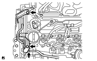
Disconnect the vacuum hose.
-
Remove the 2 bolts and 2 harness brackets.
-
-
REMOVE CYLINDER HEAD COVER SUB-ASSEMBLY
-
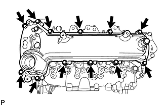
Remove the 12 bolts and cylinder head cover.
-
-
CHECK VALVE CLEARANCE
-
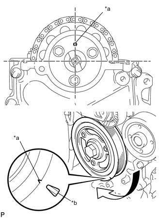
Text in Illustration *a Timing Mark *b TDC Mark Set the No. 1 cylinder to TDC/Compression.
-
Turn the crankshaft pulley until the grooves of the crankshaft damper and oil pump are aligned.
-
Check that the timing mark of the camshaft timing sprocket is in the position shown in the illustration.
Tech Tips
If not, turn the crankshaft damper 1 revolution (360°) to align the timing mark and sprocket as above.
-
-
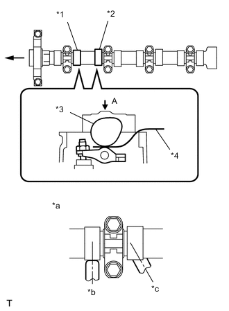
Text in Illustration *1 No. 1 Exhaust *2 No. 2 Intake *3 Camshaft *4 Feeler Gauge *a View A *b OK *c NG Check the valve clearance of the No. 1 cylinder exhaust valve and the No. 2 cylinder intake valve.
-
Using a feeler gauge, measure the clearance between the camshaft and No. 1 valve rocker arm.
Valve clearance (cold) 0.11 to 0.17 mm (0.004 to 0.007 in.) for intake 0.14 to 0.20 mm (0.006 to 0.008 in.) for exhaust Note
-
Insert the feeler gauge into the center of the roller surface, parallel to the No. 1 valve rocker arm.
-
Do not apply excessive force to the valve adjusting screw when using adjusting tools such as SST and a screwdriver.
Tech Tips
If the clearance is not as specified, record the out-of-specification measurement, and then adjust the valve clearance.
-
-
-
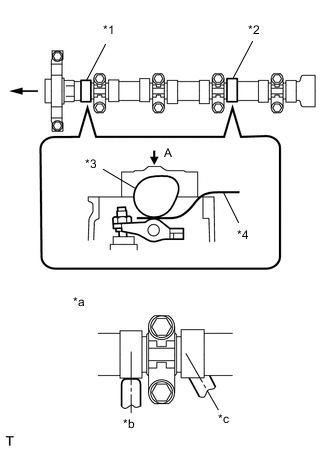
Text in Illustration *1 No. 1 Intake *2 No. 3 Exhaust *3 Camshaft *4 Feeler Gauge *a View A *b OK *c NG Check the valve clearance of the No. 1 cylinder intake valve and the No. 3 cylinder exhaust valve.
-
Turn the crankshaft by a further 180° clockwise.
-
Using a feeler gauge, measure the clearance between the camshaft and No. 1 valve rocker arm as shown in the illustration.
Valve clearance (cold) 0.11 to 0.17 mm (0.004 to 0.007 in.) for intake 0.14 to 0.20 mm (0.006 to 0.008 in.) for exhaust Note
-
Insert the feeler gauge into the center of the roller surface, parallel to the No. 1 valve rocker arm.
-
Do not apply excessive force to the valve adjusting screw with adjusting tools when measuring or adjusting.
Tech Tips
If the clearance is not as specified, record the out-of-specification measurement, and then adjust the valve clearance.
-
-
-
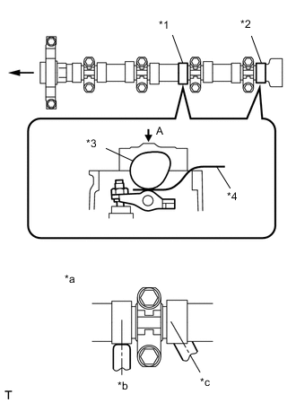
Text in Illustration *1 No. 3 Intake *2 No. 4 Exhaust *3 Camshaft *4 Feeler Gauge *a View A *b OK *c NG Check the valve clearances of the No. 3 cylinder intake valve and No. 4 cylinder exhaust valve.
-
Turn the crankshaft clockwise by a further 180°.
-
Using a feeler gauge, measure the clearance between the camshaft and No. 1 valve rocker arm as shown in the illustration.
Valve clearance (cold) 0.11 to 0.17 mm (0.004 to 0.007 in.) for intake 0.14 to 0.20 mm (0.006 to 0.008 in.) for exhaust Note
-
Insert the feeler gauge into the center of the roller surface, parallel to the No. 1 valve rocker arm.
-
Do not apply excessive force to the valve adjusting screw with adjusting tools when measuring or adjusting.
Tech Tips
If the clearance is not as specified, record the out-of-specification measurement, and then adjust the valve clearance.
-
-
-
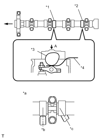
Text in Illustration *1 No. 2 Exhaust *2 No. 4 Intake *3 Camshaft *4 Feeler Gauge *a View A *b OK *c NG Check the valve clearances of the No. 2 cylinder intake valve and No. 4 cylinder intake valve.
-
Turn the crankshaft clockwise by a further 180°.
-
Using a feeler gauge, measure the clearance between the camshaft and No. 1 valve rocker arm.
Valve clearance (cold) 0.11 to 0.17 mm (0.004 to 0.007 in.) for intake 0.14 to 0.20 mm (0.006 to 0.008 in.) for exhaust Note
-
Insert the feeler gauge into the center of the roller surface, parallel to the No. 1 valve rocker arm.
-
Do not apply excessive force to the valve adjusting screw with adjusting tools when measuring or adjusting.
Tech Tips
If the clearance is not as specified, record the out-of-specification measurement, and then adjust the valve clearance.
-
-
-
-
ADJUST VALVE CLEARANCE
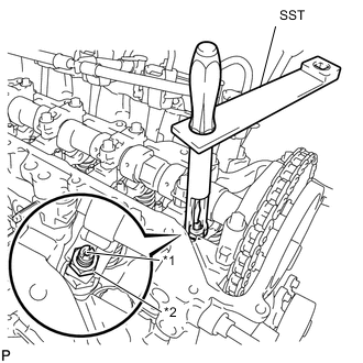
Text in Illustration *1 Adjusting Screw *2 Lock Nut
-
Using SST and a screwdriver, loosen the valve adjusting nut while keeping the valve adjusting screw in position.
- SST
- 09248-56010
-
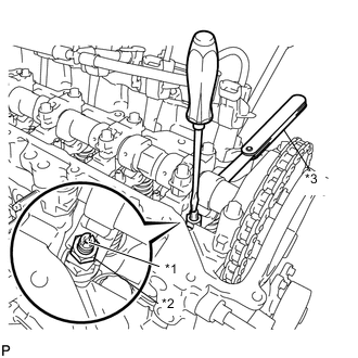
Text in Illustration *1 Adjusting Screw *2 Lock Nut *3 Feeler Gauge Adjust valve clearance (intake side).
-
Insert a thickness gauge (0.14 mm (0.006 in.)) between the camshaft and No. 1 valve rocker arm, and turn the valve adjusting screw to adjust it.
Valve clearance (cold) 0.14 mm (0.006 in.) -
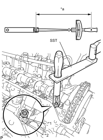
Text in Illustration *1 Adjusting Screw *2 Lock Nut *a Fulcrum Length Using SST and a screwdriver, tighten the valve adjusting nut while keeping the valve adjusting screw in position.
- Torque:
- With SST
- 13 N*m { 133 kgf*cm, 10 ft.*lbf }
- Without SST
- 20 N*m { 204 kgf*cm, 15 ft.*lbf }
Tech Tips
-
This torque wrench value can be obtained by using a torque wrench with a fulcrum length of 300 mm (11.81 in.) and SST with a fulcrum length of 150 mm (5.91 in.) Click here.
-
This torque value is effective when SST is parallel to a torque wrench.
-
-
Adjust the valve clearance (exhaust side).
Valve clearance (cold) 0.17 mm (0.007 in.) Tech Tips
Perform the same procedure as for the intake valve clearance adjustment.
-
-
INSTALL CYLINDER HEAD COVER SUB-ASSEMBLY
-
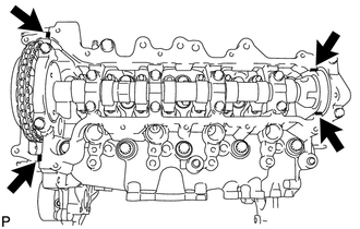
Apply seal packing to the 4 locations as shown in the illustration, and then install the cylinder head cover.
Text in Illustration 
Seal Packing Seal packing Toyota Genuine Seal Packing Black, Three Bond 1207B or equivalent Note
-
Remove any oil from the contact surface.
-
Install the cylinder head cover within 3 minutes, and tighten the bolts within 15 minutes of applying the seal packing.
-
-
Temporarily tighten the cylinder head cover with the 12 bolts.
-
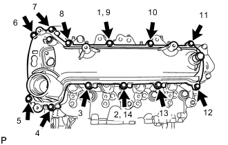
Fully tighten the 12 bolts, in the order shown in the illustration.
- Torque:
- 11 N*m { 112 kgf*cm, 8 ft.*lbf }
-
-
INSTALL HARNESS BRACKET
-
Install the 2 harness brackets with the 2 bolts.
- Torque:
- 8.4 N*m { 85 kgf*cm, 74 in.*lbf }
-
Connect the vacuum hose.
-
-
INSTALL NO. 2 CYLINDER HEAD COVER

-
Install the No. 2 cylinder head cover.
-
Install the fuel check valve onto the No. 2 cylinder head cover.
-
Install the 3 nozzle leakage pipe set clamps.
-
-
INSTALL SENSOR BRACKET
-
Install the sensor bracket with the nut.
- Torque:
- 8.0 N*m { 82 kgf*cm, 71 in.*lbf }
-
-
INSTALL NO. 2 ENGINE COVER BRACKET
-
Install the air fuel ratio sensor bracket and the harness bracket.
-
Install the No. 2 engine cover bracket with the 2 nuts.
- Torque:
- 11 N*m { 112 kgf*cm, 8 ft.*lbf }
-
-
INSTALL VENTILATION HOSE
-
Install the ventilation hose.
-
-
INSTALL VACUUM PUMP ASSEMBLY
-
CONNECT ENGINE WIRE
-
INSTALL NO. 1 ENGINE COVER
-
INSTALL ENGINE UNDER COVER RH
-
INSTALL CENTER ENGINE UNDER COVER
-
CONNECT CABLE TO NEGATIVE BATTERY TERMINAL
- Torque:
- 5.4 N*m { 55 kgf*cm, 48 in.*lbf }