REAR CRANKSHAFT OIL SEAL INSTALLATION

CAUTION / NOTICE / HINT
Note
When the transaxle is removed, be sure to use a new clutch release with bearing cylinder and new installation bolts. Removal of the transaxle allows the compressed clutch release with bearing cylinder to return to its original position, and dust from the moving section could damage the seal of the clutch release with bearing cylinder, possibly causing clutch fluid leaks.
PROCEDURE
-
INSTALL REAR ENGINE OIL SEAL (for CVT)
-
Remove any old packing material and be careful not to drop any oil on the contact surfaces of the oil pan and cylinder block.
-
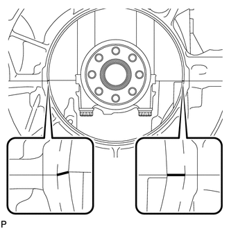
Apply seal packing in a continuous bead as shown in the illustration.
Seal packing Toyota Genuine Seal Packing Black, Three Bond 1207B or equivalent Note
-
Remove any oil from the contact surfaces.
-
Install a new rear engine oil seal within 3 minutes after applying seal packing.
-
Do not start the engine for at least 2 hours after installing.
-
-
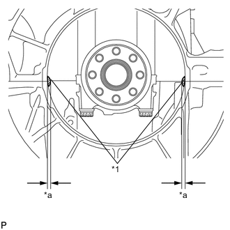
Text in Illustration *1 Seal Packing *a 2.0mm (0.0787in.) Wipe off the excess seal packing, leaving only the specified amount in the areas shown in the illustration.
-
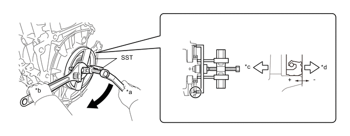
Using SST, press in a new rear engine oil seal until its surface is flush with the cylinder block sub-assembly and oil pan sub-assembly.
- SST
- 09223-47020
- 09950-50013 ( 09951-05010, 09952-05010, 09953-05020, 09954-05021, 09955-05010, 09957-04010 )
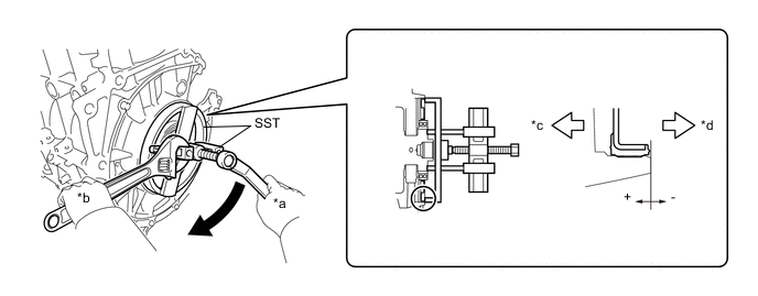
Text in Illustration *a Turn *b Hold *c Engine Front *d Engine Rear Oil seal standard depth -0.2 to 1.2 mm (-0.0079 to 0.0472 in.) Note
-
Make sure there is no foreign matter on the lip of the rear engine oil seal.
-
Make sure there is no oil or grease on the outer circumference of the rear engine oil seal.
-
Do not press in the rear engine oil seal at an angle.
-
Wipe off extra grease from the crankshaft.
-
Apply a small amount of molybdenum grease to the threaded portion and tip of SST center bolt (09953-05020) before using.
Tech Tips
If necessary, lightly tap SST using a plastic-faced hammer to insert the rear engine oil seal evenly.
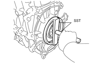
- SST
- 09950-70010 ( 09951-07150 )
- 09223-47020
-
-
INSTALL REAR ENGINE OIL SEAL (w/ Stop And Start System)
-
Remove any old packing material and be careful not to drop any oil on the contact surfaces of the oil pan and cylinder block.
-
Apply seal packing in a continuous bead as shown in the illustration.
Seal packing Toyota Genuine Seal Packing Black, Three Bond 1207B or equivalent Note
-
Remove any oil from the contact surfaces.
-
Install a new rear engine oil seal within 3 minutes after applying seal packing.
-
Do not start the engine for at least 2 hours after installing.
-
-
Text in Illustration *1 Seal Packing *a 2.0mm (0.0787in.) Wipe off the excess seal packing, leaving only the specified amount in the areas shown in the illustration.
-
Using SST, press in a new rear engine oil seal until its surface is flush with the cylinder block sub-assembly and oil pan sub-assembly.
- SST
- 09223-47020
- 09950-50013 ( 09951-05010, 09952-05010, 09953-05020, 09954-05021, 09955-05010, 09957-04010 )
Text in Illustration *a Turn *b Hold *c Engine Front *d Engine Rear Oil seal standard depth -0.2 to 1.2 mm (-0.0079 to 0.0472 in.) Note
-
Make sure there is no foreign matter on the lip of the rear engine oil seal.
-
Make sure there is no oil or grease on the outer circumference of the rear engine oil seal.
-
Do not press in the rear engine oil seal at an angle.
-
Wipe off extra grease from the crankshaft.
-
Apply a small amount of molybdenum grease to the threaded portion and tip of SST center bolt (09953-05020) before using.
Tech Tips
If necessary, lightly tap SST using a plastic-faced hammer to insert the rear engine oil seal evenly.
- SST
- 09950-70010 ( 09951-07150 )
- 09223-47020
-
-
INSTALL REAR ENGINE OIL SEAL (for Manual Transaxle)
Tech Tips
Use the same procedure for CVT.
-
INSTALL INNER OIL SEAL (w/ Stop and Start System)
-
Apply MP grease to the lip of a new inner oil seal.
Note
Keep the lip free from foreign matter.
-
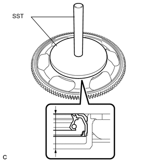
Using SST and a hammer, tap in the inner oil seal until its surface is flush with the ring gear sub-assembly.
Oil seal tap in depth 14.7 to 15.7 mm (0.5787 to 0.6181 in.) - SST
- 09950-70010 ( 09951-07150 )
- 09951-01600
Note
-
Uniformly tap in the oil seal.
-
Do not tap the oil seal at an angle.
-
-
INSTALL RING GEAR SUB-ASSEMBLY (w/ Stop and Start System)
-
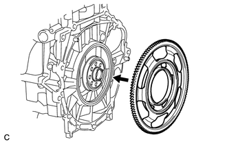
Install the ring gear sub-assembly.
Note
-
Do not apply excessive force to the ring gear sub-assembly.
-
Be sure not to allow any foreign matter, oil or grease to adhere to the sliding part of the engine rear oil seal.
-
Be sure not to allow any foreign matter to adhere to the lip of the engine rear oil seal.
-
-
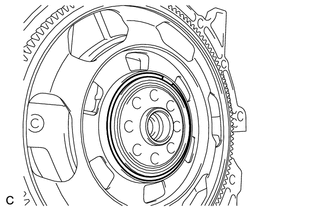
Using a screwdriver, install the snap ring.
Note
Confirm that the snap ring is correctly located in the groove of the crankshaft bearing.
-
-
INSTALL ONE-WAY CLUTCH ASSEMBLY (w/ Stop and Start System)
-
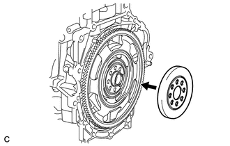
Turn the one-way clutch assembly counterclockwise while installing it.
Note
-
Be sure not to allow any foreign matter, oil or grease to adhere to the installation surfaces of the crankshaft and the one-way clutch.
-
Be sure not to allow any foreign matter, oil or grease to adhere to the sliding surface of the inner oil seal.
-
Be sure not to allow any foreign matter to adhere to the lip of the inner oil seal.
-
-
-
INSTALL FLYWHEEL SUB-ASSEMBLY (for Manual Transaxle)
-
Using SST, hold the crankshaft.
- SST
- 09960-10010 ( 09962-01000, 09963-01000 )
-
Clean the bolts and bolt holes.
-
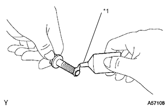
Text in Illustration *1 Adhesive Apply adhesive to 2 or 3 end threads at the end of each of the 8 bolts.
Adhesive Toyota Genuine Adhesive 1324, Three Bond 1324 or equivalent -
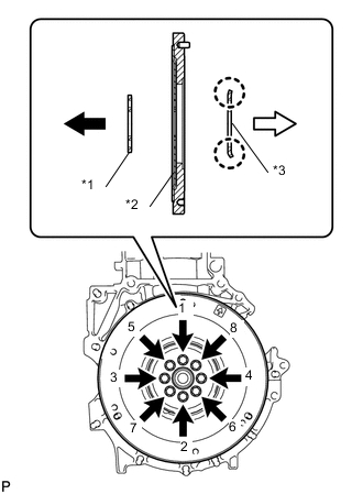
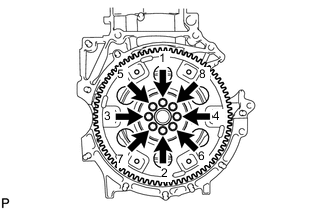
Text in Illustration *1 Front Flywheel Plate Spacer *2 Flywheel *3 Rear Flywheel Plate Spacer 
Engine 
Transaxle Install and uniformly tighten the 8 bolts in several steps in the sequence shown in the illustration.
Tech Tips
-
The front drive plate spacer is reversible.
-
As the rear drive plate spacer and the drive plate and ring gear are not reversible, be sure to install them so that they are facing in the direction shown in the illustration.
- Torque:
- 78 N*m { 795 kgf*cm, 57 ft.*lbf }
Note
Do not start the engine for at least an hour after installing the flywheel sub-assembly.
-
-
-
INSTALL FLYWHEEL SUB-ASSEMBLY (w/ Stop And Start System)
Tech Tips
Use the same procedure for manual transaxle.
-
INSTALL DRIVE PLATE AND RING GEAR SUB-ASSEMBLY (for CVT)
-
Using SST, hold the crankshaft.
- SST
- 09960-10010 ( 09962-01000, 09963-01000 )
-
Clean the bolts and bolt holes.
-
Text in Illustration *1 Adhesive Apply adhesive to 2 or 3 end threads at the end of each of the 8 bolts.
Adhesive Toyota Genuine Adhesive 1324, Three bond 1324 or equivalent -
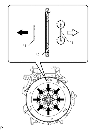
Text in Illustration *1 Front Flywheel Plate Spacer *2 Drive Plate *3 Rear Flywheel Plate Spacer Engine Transaxle Install and uniformly tighten the 8 bolts in several steps in the sequence shown in the illustration.
Tech Tips
-
The front drive plate spacer is reversible.
-
As the rear drive plate spacer and the drive plate and ring gear are not reversible, be sure to install them so that they are facing in the direction shown in the illustration.
-
-
Fully tighten the 8 bolts in the order shown in the illustration.
- Torque:
- 78 N*m { 795 kgf*cm, 57 ft.*lbf }
Note
Do not start the engine for at least an hour after installing the drive plate.
-
-
INSTALL CLUTCH DISC ASSEMBLY (for Manual Transmission)
-
INSTALL CONTINUOUSLY VARIABLE TRANSAXLE ASSEMBLY (for CVT)