REAR CRANKSHAFT OIL SEAL REMOVAL

CAUTION / NOTICE / HINT
Note
When the transaxle is removed, be sure to use a new clutch release with bearing cylinder and new installation bolts. Removal of the transaxle allows the compressed clutch release with bearing cylinder to return to its original position, and dust from the moving section could damage the seal of the clutch release with bearing cylinder, possibly causing clutch fluid leaks.
PROCEDURE
-
REMOVE CONTINUOUSLY VARIABLE TRANSAXLE ASSEMBLY (for CVT)
-
REMOVE CLUTCH DISC ASSEMBLY (for Manual Transmission)
-
REMOVE DRIVE PLATE AND RING GEAR SUB-ASSEMBLY (for CVT)
-
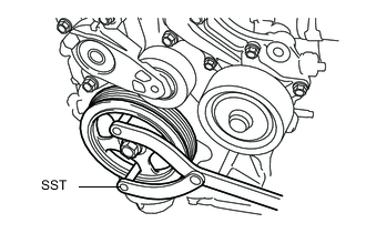
Using SST, hold the crankshaft.
-
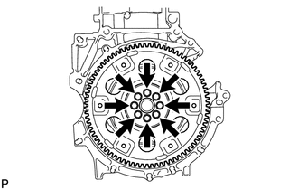
Remove the 8 bolts, the rear drive plate spacer, the drive plate and the front drive plate spacer.
-
-
REMOVE FLYWHEEL SUB-ASSEMBLY (for Manual Transmission)
-
Using SST, hold the crankshaft.
- SST
- 09960-10010 ( 09962-01000, 09963-01000 )
-
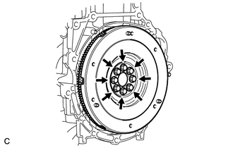
Remove the 8 bolts and flywheel sub-assembly.
-
-
REMOVE FLYWHEEL SUB-ASSEMBLY (w/ Stop And Start System)
Tech Tips
Use the same procedure for manual transmission.
-
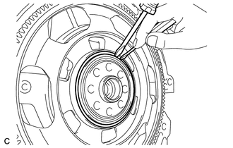
REMOVE INNER OIL SEAL (w/ Stop and Start System)
-
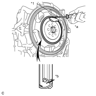
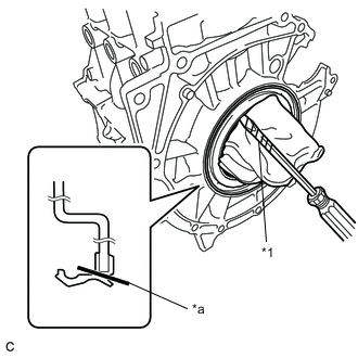
Text in Illustration *1 Protective Tape *a Pry Out *b Cut Position Using a knife, cut off the lip of the inner oil seal.
-
Using a screwdriver with its tip wrapped with protective tape, pry out the inner oil seal.
Note
Be careful not to damage the one-way clutch assembly.
-
-
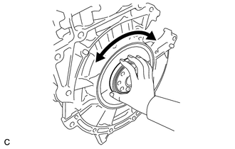
REMOVE ONE-WAY CLUTCH ASSEMBLY (w/ Stop and Start System)
-
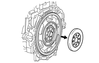
Turn the one-way clutch assembly counterclockwise while removing it.
-
-
INSPECT RING GEAR SUB-ASSEMBLY (w/ Stop and Start System)
-
Visually check the one-way clutch assembly installation surface for damage, deformation, and cracks.
-
Check that the snap ring is not broken and fits correctly into the crankshaft bearing groove.
-
-
REMOVE RING GEAR SUB-ASSEMBLY (w/ Stop and Start System)
-
Using a screwdriver, remove the snap ring.
-
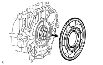
Remove the ring gear sub-assembly from the crankshaft.
Note
Do not forcefully pry the ring gear during removal.
-
-
INSPECT ONE-WAY CLUTCH ASSEMBLY (w/ Stop and Start System)
-
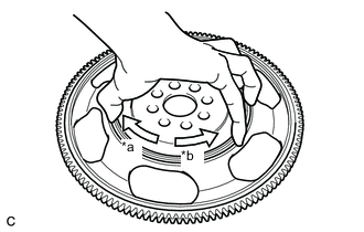
Text in Illustration *a Lock *b Free Make sure that the one-way clutch assembly turns freely counterclockwise and locks when turned clockwise.
If the one-way clutch assembly does not operate normally, replace it.
-
-
INSPECT CRANKSHAFT BEARING (w/ Stop and Start System)
-
Turn the crankshaft bearing by hand and check if it turns smoothly.
If the bearing does not move smoothly and noiselessly, replace the crankshaft bearing.
-
-
REMOVE REAR ENGINE OIL SEAL (for CVT)
-
Text in Illustration *1 Protective Tape *a Cut Position Using a knife, cut off the oil seal lip.
-
Using a screwdriver with its tip wrapped with protective tape, pry out the rear engine oil seal.
-
-
REMOVE REAR ENGINE OIL SEAL (w/ Stop and Start System)
-
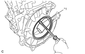
Text in Illustration *1 Protective Tape Using a screwdriver with its tip wrapped with protective tape, pry out the rear engine oil seal.
Note
-
If the snap ring is broken, the ring gear may move out from its original position and result in an oil leak. Therefore, it is necessary to confirm that the snap ring is installed correctly and undamaged when replacing the oil seal.
-
Be careful not to damage the crankshaft bearing.
-
-
-
REMOVE REAR ENGINE OIL SEAL (w/o Stop and Start System)
Tech Tips
Use the same procedure for CVT.