CAMSHAFT INSTALLATION
PROCEDURE
-
INSTALL VALVE LASH ADJUSTER ASSEMBLY
-
INSTALL NO. 1 VALVE ROCKER ARM SUB-ASSEMBLY
-
INSTALL CAMSHAFT
-
Clean the camshaft journals.
-
Apply a light coat of engine oil to the camshaft journals and camshaft housing.
-
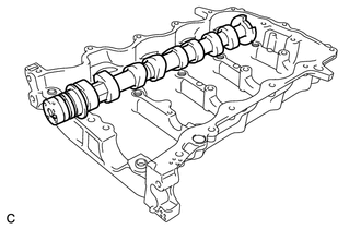
Install the camshaft to the camshaft housing.
-
-
INSTALL NO. 2 CAMSHAFT
-
Clean the camshaft journals.
-
Apply a light coat of engine oil to the camshaft journals and camshaft housing.
-
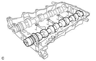
Install the No. 2 camshaft to the camshaft housing.
-
-
INSTALL CAMSHAFT BEARING CAP
-
Apply engine oil to the bearing caps.
-
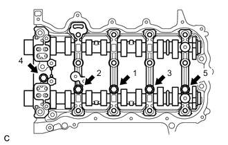
Install the 5 bearing caps to the camshaft housing.
-
Tighten the 5 bolts in the order shown in the illustration.
- Torque:
- 16 N*m { 163 kgf*cm, 12 ft.*lbf }
-
-
INSTALL CAMSHAFT HOUSING SUB-ASSEMBLY
-
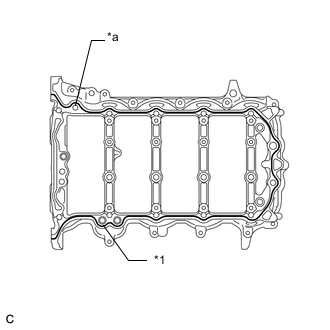
Text in Illustration *1 Seal Packing *a Bead diameter 3.5 to 4.0 mm Apply seal packing in a continuous bead as shown in the illustration.
Seal packing Toyota Genuine Seal Packing Black, Three Bond 1280E or equivalent Bead diameter 3.5 to 4.0 mm (0.138 to 0.158 in.) Note
-
Remove any oil from the contact surfaces.
-
Install the camshaft housing sub-assembly within 3 minutes and tighten the bolts within 15 minutes after applying seal packing.
-
Do not start the engine for at least 2 hours after installing.
-
-
Text in Illustration *1 Timing Mark Set the crankshaft in the position (40° BTDC) shown in the illustration.
Note
Turn the crankshaft clockwise when positioning the No. 1 cylinder after the camshaft housing sub-assembly is installed.
Tech Tips
Make sure that the timing mark of the crankshaft is positioned as shown in the illustration.
-
Set the camshaft and No. 2 camshaft as shown in the illustration.
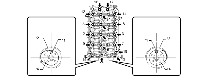
Text in Illustration *1 Straight Pin *2 Camshaft *3 No. 2 Camshaft *4 No. 1 Cylinder Cam Tech Tips
Make sure that the straight pin of the camshaft is positioned as shown in the illustration.
-
Install the camshaft housing and tighten the 18 bolts in the order shown in the illustration.
- Torque:
- 28 N*m { 285 kgf*cm, 21 ft.*lbf }
Note
-
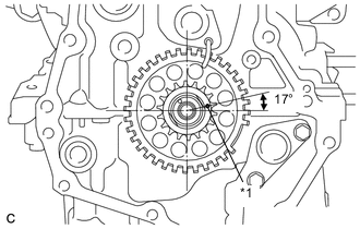
After installing the camshaft housing, make sure that the cam lobes are positioned as shown in the illustration.
-
If any of the bolts are loosened during installation, remove the camshaft housing, clean the installation surfaces, and reapply seal packing.
-
If the camshaft housing is removed because any of the bolts are loosened during installation, make sure that the previously applied seal packing does not enter any oil passages.
-
After installing the camshaft housing, wipe off any seal packing that seeped out from between the housing and the cylinder head.
-
-
INSTALL CAMSHAFT TIMING GEAR ASSEMBLY
-
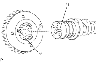
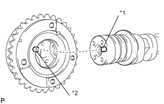
Text in Illustration *1 Straight Pin *2 Straight Pin Hole Check that the straight pin is installed on the camshaft.
-
Put the camshaft timing gear and camshaft together by aligning the straight pin hole and straight pin.
Note
-
Do not forcefully push in the camshaft timing gear assembly. This may cause the camshaft straight pin tip to damage the installation surface of the camshaft timing gear assembly.
-
Do not turn the camshaft timing gear in the retard direction (clockwise).
-
-
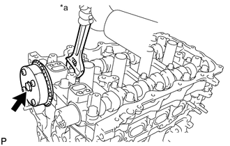
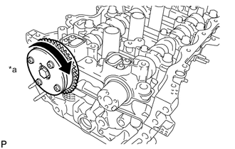
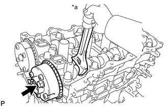
Text in Illustration *a Hold Tighten the flange bolt with the camshaft timing gear secured in place.
- Torque:
- 54 N*m { 551 kgf*cm, 40 ft.*lbf }
-
Text in Illustration *a Lock Check that the camshaft timing gear can move in the retard direction (clockwise) and locks in the most retarded position.
-
-
INSTALL CAMSHAFT TIMING EXHAUST GEAR ASSEMBLY
-
Text in Illustration *1 Straight Pin *2 Straight Pin Hole Check that the straight pin is installed on the No. 2 camshaft.
-
Put the camshaft timing exhaust gear and No. 2 camshaft together by aligning the straight pin hole and straight pin.
Note
Do not forcefully push in the camshaft timing gear assembly. This may cause the camshaft straight pin tip to damage the installation surface of the camshaft timing gear assembly.
-
Text in Illustration *a Hold Tighten the flange bolt with the camshaft timing exhaust gear secured in place.
- Torque:
- 54 N*m { 551 kgf*cm, 40 ft.*lbf }
-
Make sure that the camshaft timing exhaust gear is locked.
-
-
INSTALL TIMING CHAIN GUIDE
-
INSTALL CHAIN SUB-ASSEMBLY
-
INSTALL TIMING CHAIN TENSION ARM
-
INSTALL NO. 1 CHAIN TENSIONER ASSEMBLY
-
INSTALL TIMING CHAIN COVER OIL SEAL
-
INSTALL TIMING CHAIN COVER SUB-ASSEMBLY
-
INSTALL CRANKSHAFT PULLEY
-
INSTALL CRANKSHAFT POSITION SENSOR
-
INSTALL NO. 2 WATER INLET HOUSING GASKET
-
INSTALL WATER INLET
-
INSTALL CYLINDER HEAD COVER SUB-ASSEMBLY
-
INSTALL V-RIBBED BELT TENSIONER ASSEMBLY
-
INSTALL NO. 1 WATER BY-PASS PIPE
-
INSTALL NO. 2 VENTILATION HOSE
-
INSTALL VENTILATION HOSE
-
INSTALL IGNITION COIL ASSEMBLY
-
INSTALL EGR VALVE ASSEMBLY
-
INSTALL NO. 1 INTAKE MANIFOLD TO HEAD GASKET
-
INSTALL INTAKE MANIFOLD
-
INSTALL EGR PIPE CONNECTOR
-
INSTALL THROTTLE WITH MOTOR BODY ASSEMBLY
-
INSTALL NO. 1 DELIVERY PIPE SPACER
-
INSTALL FUEL INJECTOR ASSEMBLY
-
INSTALL FUEL DELIVERY PIPE
-
INSTALL EXHAUST MANIFOLD CONVERTER SUB-ASSEMBLY
-
INSTALL MANIFOLD STAY
-
INSTALL NO. 2 EXHAUST MANIFOLD HEAT INSULATOR
-
INSTALL NO. 1 EXHAUST MANIFOLD HEAT INSULATOR
-
INSTALL ENGINE OIL LEVEL DIPSTICK GUIDE
-
INSTALL OIL LEVEL DIPSTICK SUB-ASSEMBLY
-
SUSPEND ENGINE ASSEMBLY
-
REMOVE ENGINE FROM ENGINE STAND