SFI SYSTEM, Diagnostic DTC:P1603, P1605
| DTC Code | DTC Name |
|---|---|
| P1603 | Engine Stall History |
| P1605 | Rough Idling |
DESCRIPTION
- P1603
After starting the engine, this DTC is stored when the engine stops without the ignition switch being operated.
Using the intelligent tester, the conditions present when the DTC was stored can be confirmed by referring to the freeze frame data. Freeze frame data records engine conditions when a malfunction occurs. This information can be useful when troubleshooting.
It is necessary to check if the vehicle has run out of fuel before performing troubleshooting, as this DTC is also stored when the engine stalls due to running out of fuel.
| DTC No. | DTC Detection Condition | Trouble Area |
|---|---|---|
| P1603 | After monitoring for startability problems (P1604) finishes and 5 seconds or more elapse after starting the engine, with the engine running, the engine stops (the engine speed drops to 200 rpm or less) without the ignition switch being operated for 0.5 seconds or more (1 trip detection logic) |
|
- P1605
This DTC is stored if the engine speed drops below the set speed.
Using the intelligent tester, the conditions present when the DTC was stored can be confirmed by referring to the freeze frame data. Freeze frame data records engine conditions when a malfunction occurs. This information can be useful when troubleshooting.
It is necessary to check if the vehicle ran out of fuel before performing troubleshooting, as this DTC is also stored when idling is unstable due to running out of fuel.
| DTC No. | DTC Detection Condition | Trouble Area |
|---|---|---|
| P1605 | After 5 seconds or more elapse after starting the engine, with the engine running, the engine speed drops to 400 rpm or less (1 trip detection logic) |
|
-
Reference waveforms showing a normal cold engine start
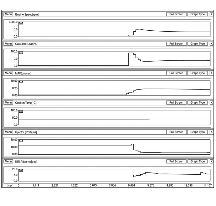
-
Reference waveforms showing a normal warm engine start
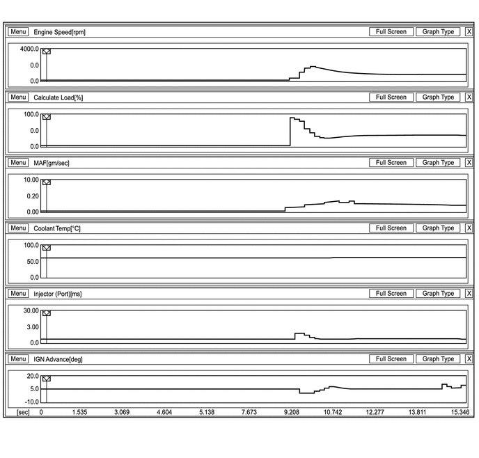
-
Reference values when there is an air leak in the intake system during rough idling
Freeze Frame Data P1605 Rough Idling Parameter -3 -2 -1 0 1 Unit Engine Speed 606 610 572 346 114 rpm Calculate Load 35.6 35.6 36.0 40.7 87.0 % Vehicle Load 19.6 19.2 20.3 60.7 120.3 % MAF 1.56 1.56 1.56 2.76 1.81 gm/sec Atmosphere Pressure 99 99 99 99 99 kPa Coolant Temp 85 85 85 85 85 °C Intake Air 40 40 40 40 40 °C Ambient Temperature 25 25 25 25 25 °C Battery Voltage 13.9 13.8 13.8 13.4 13.3 V Throttle Sensor Volt % 14.9 14.9 14.9 16.0 15.2 % Throttle Sensor #2 Volt % 46.6 46.6 46.6 48.2 47.4 % Throttle Sensor Position 0.0 0.0 0.0 0.0 0.0 % Throttle Motor DUTY 14.9 14.9 14.9 16.4 15.2 % Injector (Port) 2.4 2.4 2.3 2.5 7.4 ms Injection Volume (Cylinder 1) 0.070 0.070 0.070 0.070 0.070 ml Fuel Pump/Speed Status ON ON ON ON ON EVAP (Purge) VSV 0.0 0.0 0.0 0.0 0.0 % Evap Purge Flow 0.0 0.0 0.0 0.0 0.0 % Purge Density Learn Value 0.000 0.000 0.000 0.000 0.000 EVAP purge VSV OFF OFF OFF OFF OFF Target Air-Fuel Ratio 0.999 0.999 0.999 0.999 0.819 AF Lambda B1 S1 1.002 1.002 1.001 1.001 1.002 AFS Voltage B1 S1 3.31 3.31 3.30 3.30 3.31 V O2S B1 S2 0.070 0.070 0.070 0.070 0.070 V Short FT #1 0.700 0.700 0.700 0.700 0.700 % Long FT #1 -1.652 -1.652 -1.652 -1.652 -1.652 % Total FT #1 -0.004 -0.004 -0.004 -0.004 -0.004 Fuel System Status #1 CL CL CL CL OL IGN Advance 5.5 4.5 6.5 4.0 4.0 deg Knock Feedback Value -3.0 -3.0 -3.0 -3.0 -3.0 CA Knock Correct Learn Value 14.0 14.0 14.0 14.0 14.0 CA VVT Control Status #1 OFF OFF OFF OFF OFF Starter Signal OFF OFF OFF OFF OFF
CAUTION / NOTICE / HINT
Tech Tips
-
In contrast to normal malfunction diagnosis for components, circuit and systems, DTCs P1603 and P1605 are used to determine the malfunctioning area from the problem symptoms and freeze frame data when the user mentions problems such as engine stall.
As these DTCs can be stored as a result of certain user actions, even if these DTCs are output, if the customer makes no mention of problems, clear these DTCs without performing any troubleshooting and return the vehicle to the customer.
-
If any other DTCs are output, perform troubleshooting for those DTCs first.
-
Use any information from the customer problem analysis about the condition of the vehicle at the time when the problem occurred (how the engine stopped, conditions when the engine was restarted, etc.) as a reference.
Symptom Suspected Area Engine vibration occurs and engine stops Air-fuel ratio abnormal Engine stops with no engine vibration Ignition system, injection stoppage, high load from external parts Engine can be started with accelerator pedal depressed Insufficient air volume Rough idling after engine started Air-fuel ratio abnormal, abnormal combustion -
Read freeze frame data using the intelligent tester. Freeze frame data records engine conditions when a malfunction occurs. This information can be useful when troubleshooting.
-
When confirming the freeze frame data, be sure to check all 5 sets of freeze frame data Click here.
-
When DTC P1603 (Engine Stall History) is stored, DTC P1605 (Rough Idling) is also stored. When confirming freeze frame data, check DTC P1605. (The ECM stores DTC P1605 first. Therefore, the 5 sets of freeze frame data can be confirmed through DTC P1605, enabling the technician to obtain more information.)
-
When confirming freeze frame data, if there are multiple items related to the cause of the malfunction, perform troubleshooting for all related items.
-
Try to operate the vehicle under the conditions recorded in the freeze frame data which were present when the malfunction occurred. Confirm the data at this time and the data when the engine is idling (engine warmed up, no load, and shift lever in D or N) and compare these data with the freeze frame data.
-
Inspections take into account the fact that the malfunction may not have reoccurred and place emphasis on checking the vehicle conditions present at the time when the malfunction occurred.
-
When performing inspections, jiggle the relevant wire harness and connectors in an attempt to reproduce malfunctions that do not always occur.
| Inspection flow |
|---|
| Using freeze frame data, narrow down the parts to be inspected according to the vehicle conditions at the time when the malfunction occurred. |
- P1603
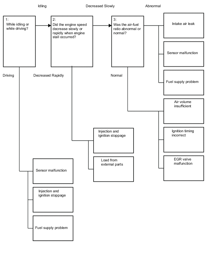
- 1:
-
If the engine stalled when the intake air volume was low (during idling or deceleration), there may be a decrease in torque due to an incorrect air-fuel ratio, etc.
-
If the engine stalled when the intake air volume was high (during driving or acceleration), there may be a major malfunction such as continuous misfire due to ignition stoppage, fuel injection stoppage, etc. and the torque drops to zero.
- 2:
-
If the engine speed decreased slowly, there may have been a decrease in torque due to an air-fuel ratio that was incorrect (by approximately 20 to 30%), etc.
-
If the engine speed decreased rapidly, there may have been a malfunction such as when the engine misfires almost continuously due to ignition stoppage, fuel injection stoppage, etc., or when the external load increases due to an external part malfunctioning.
- 3:
-
If the air-fuel ratio was abnormal, there may have been an intake air leak, sensor malfunction, or fuel supply problem.
-
If the air-fuel ratio was normal, the air volume may have been insufficient, the ignition timing may have been incorrect or the EGR valve may have been stuck open.
P1603 inspection flow: Narrow down the parts to be inspected according to the vehicle conditions at the time when the malfunction occurred (freeze frame data).
| Vehicle State | Engine Speed | Suspected Area | Primary Parts to Inspect | Procedure | |
|---|---|---|---|---|---|
| Idling or decelerating | Slowly decreases and engine stalls | Air-fuel ratio abnormal | Air suction |
|
3 to 6 |
| Sensor malfunction (value from sensor too lean) |
|
7 to 16 | |||
| Sensor malfunction (value from sensor too rich) | 25 to 34 | ||||
| Fuel supply problem |
|
17 to 24 | |||
| Intake air volume insufficient | ISC flow rate |
|
35 to 37 | ||
| Excessive valve overlap |
|
38 | |||
| Abnormal combustion |
|
39, 40 | |||
| Ignition timing incorrect | Does not operate as expected |
|
42, 43 | ||
| Rapidly decreases and engine stalls | Ignition and injection stops (electrical system malfunction) | Power temporarily cut |
|
44, 45 | |
| External part malfunctioning | Increase in load |
|
48 to 50 | ||
| Accelerating | - | Crankshaft position sensor, Camshaft position sensor malfunction | Power temporarily cut |
|
1 |
| Mass air flow meter | Foreign matter adhesion |
|
51, 52 | ||
| Fuel supply problem | Fuel leak, clog |
|
55 to 57 | ||
| Ignition and injection stops (electrical system malfunction) | Power temporarily cut |
|
53, 54 | ||
- P1605:
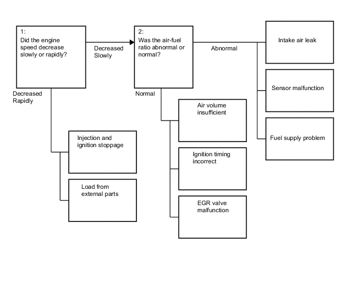
- 1:
-
If the engine speed decreased slowly, there may have been a decrease in torque due to an air-fuel ratio that was incorrect (by approximately 20 to 30%), etc.
-
If the engine speed decreased rapidly, there may have been a malfunction such as when the engine misfires almost continuously due to ignition stoppage, fuel injection stoppage, etc., or when the external load increases due to an external part malfunctioning.
- 2:
-
If the air-fuel ratio was abnormal, there may have been an intake air leak, sensor malfunction, or fuel supply problem.
-
If the air-fuel ratio was normal, the air volume may have been insufficient, the ignition timing may have been incorrect or the EGR valve may have been stuck open.
P1605 inspection flow: Narrow down the parts to be inspected according to the vehicle conditions at the time when the malfunction occurred (freeze frame data).
| Engine Speed | Suspected Area | Primary Parts to Inspect | Procedure | |
|---|---|---|---|---|
| Slowly decreases and engine stalls | Air-fuel ratio abnormal | Air suction |
|
3 to 6 |
| Sensor malfunction (value from sensor too lean) |
|
7 to 16 | ||
| Sensor malfunction (value from sensor too rich) |
25 to 34 | |||
| Fuel supply problem |
|
17 to 24 | ||
| Intake air volume insufficient | ISC flow rate |
|
35 to 37 | |
| Abnormal combustion |
|
39, 40 | ||
| Ignition timing incorrect | Does not operate as expected |
|
42, 43 | |
| Rapidly decreases and engine stalls | Ignition and injection stops (electrical system malfunction) | Power temporarily cut |
|
44, 45 |
| External part malfunctioning | Increase in load |
|
48 to 50 | |
Note
Inspect the fuses for circuits related to this system before performing the following inspection procedure.
PROCEDURE
-
CHECK ANY OTHER DTCS OUTPUT (IN ADDITION DTC P1603 AND P1605)
-
Connect the intelligent tester to the DLC3.
-
Turn the ignition switch to ON.
-
Read the DTCs.
Result Result Proceed to Only DTC P1603 and/or P1605 are output A DTCs other than P1603 and P1605 are output B
B 
GO TO DTC CHART Click here
A 
-
-
READ FREEZE FRAME DATA
-
Connect the intelligent tester to the DLC3.
-
Turn the ignition switch to ON.
-
Using the intelligent tester, confirm the vehicle conditions recorded in the freeze frame data which were present when the DTC was stored Click here.
Result Problem Symptom Freeze Frame Data Item for DTC P1605 Suspected Area Proceed to Closed Throttle Position SW Engine Speed Total of Short FT and Long FT When idling or decelerating, engine speed slowly decreases and engine stalls All 5 sets of freeze frame data are ON Decreases slowly*1 All 5 sets of freeze frame data are +15% or more*2
-
Air suction
-
Sensor malfunction (value from sensor too lean)
-
Fuel supply problem
A At least 1 of the 5 sets of freeze frame data is -15% or less*3 Sensor malfunction (value from sensor too rich) B All 5 sets of freeze frame data are from -15% to +15%
-
Intake air volume insufficient
-
Ignition timing incorrect
C When idling or decelerating, engine speed rapidly decreases and engine stalls Decreases rapidly*1 -
-
Injection stoppage, ignition stoppage
-
Load from external parts
D When accelerating or driving at constant speed and engine stalls*4 At least one is OFF - -
-
Sensor malfunction
-
Injection stoppage, ignition stoppage
-
Fuel supply problem
E 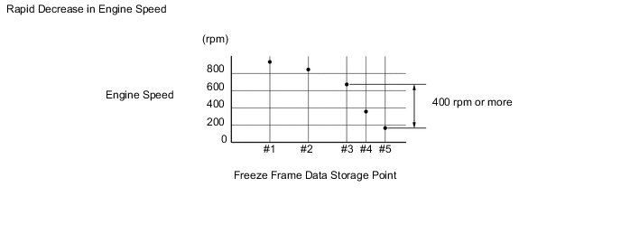
Tech Tips
-
*1: A rapid decrease in engine speed may have been caused by an electrical malfunction in the shared wiring of all or multiple cylinders, an increase in load from external parts, etc. The engine speed is considered to have decreased rapidly if either of the following conditions apply.
Otherwise, the engine speed is considered to have decreased slowly.
-
In the freeze frame data, the decrease in engine speed from #3 to #5 is 400 rpm or more.
-
In the freeze frame data, the engine speed at #5 is 120 rpm or less.
-
If the vehicle speed is 18 km/h (11 mph) or less and the difference between the Engine Speed and SPD (NOUT) is 100 rpm or less, inspect the CVT. (Depending on the rate of vehicle deceleration, the engine speed may have decreased due to the CVT lock-up release being late.)
-
*2: When a DTC is stored, feedback compensation increases because the air-fuel ratio is determined to be lean.
-
*3: When a DTC is stored, feedback compensation decreases because the air-fuel ratio is determined to be rich.
-
*4: This item should be checked when DTC P1603 is output and is not necessary to check when only P1605 is output.
-
B 
READ FREEZE FRAME DATA Click here
C
READ FREEZE FRAME DATA Click here
D
CHECK HARNESS AND CONNECTOR (FUEL INJECTOR ASSEMBLY - POWER SOURCE VOLTAGE) Click here
E
READ FREEZE FRAME DATA Click here
A
-
-
CHECK INTAKE SYSTEM
-
Check for air suction in the intake system [vacuum hose disconnection, cracks, gaskets, etc.] Click here.
Tech Tips
-
If the accelerator pedal is released after racing the engine, the inspection is easier to perform because the vacuum inside the intake pipes increases and the air suction noise becomes louder.
-
If Short FT and Long FT are largely different from the normal values when idling (the intake air volume is small) and almost the same as the normal values when racing the engine (the intake air volume is high), air suction may be present.
OK There is no air suction. -
NG
REPAIR OR REPLACE INTAKE SYSTEM
OK
-
-
INSPECT PURGE VALVE
-
Disconnect the purge hose (on the canister side) of the purge valve.
-
Start the engine.
-
Idle the engine.
-
Disconnect the connector of the purge valve.
-
Check if air flows through the purge valve.
OK Air does not flow. -
Connect the connector of the purge valve.
-
Connect the purge hose of the purge valve.
Tech Tips
When this inspection is performed, the MIL may illuminate. After finishing the inspection, check and clear DTCs Click here.
NG
INSPECT PURGE VALVE Click here
OK
-
-
READ FREEZE FRAME DATA
-
Connect the intelligent tester to the DLC3.
-
Turn the ignition switch to ON.
-
Using the intelligent tester, confirm the vehicle conditions recorded in the freeze frame data which were present when the DTC was stored Click here.
Result Freeze Frame Data Item for DTC P1605 Result Suspected Area Proceed to Stop Light Switch At least 1 of the 5 sets of freeze frame data is ON Air suction from Brake booster A All 5 sets of freeze frame data are OFF - B
B
READ FREEZE FRAME DATA Click here
A
-
-
READ VALUE USING INTELLIGENT TESTER (SHORT FT #1)
-
Connect the intelligent tester to the DLC3.
-
Turn the ignition switch to ON.
-
Start the engine, turn off all accessory switches and warm up the engine until the engine coolant temperature stabilizes.
-
Idle the engine.
-
Turn the tester on.
-
Enter the following menus: Powertrain / Engine and ECT / Data List / Short FT #1.
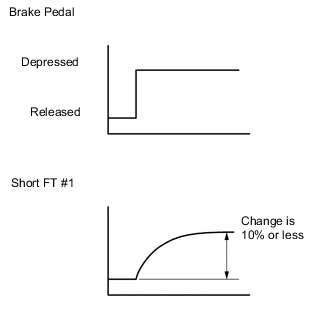
Standard Short FT #1 changes by +10% or less. Result Result Proceed to OK A NG B Tech Tips
-
Even if the results are normal, the Brake booster may have been malfunctioning. Continue this inspection procedure until step 24, and if there are no problems with other parts, replace the brake booster (refer to step 58).
-
When air suction is present, the feedback compensation increases because the air-fuel ratio becomes lean.
-
It is also possible to perform the airtightness inspection to check the brake booster.
-
B
REPLACE BRAKE BOOSTER ASSEMBLY Click here
A
-
-
READ FREEZE FRAME DATA
-
Connect the intelligent tester to the DLC3.
-
Turn the ignition switch to ON.
-
Using the intelligent tester, confirm the vehicle conditions recorded in the freeze frame data which were present when the DTC was stored Click here.
Result Freeze Frame Data Item for DTC P1605 Result Suspected Area Proceed to Calculate Load Below 90% of the current value of the vehicle*1 Mass air flow meter A AFS Voltage B1S1 3.3 V or higher*2
-
Air fuel ratio sensor
-
Wire harness or connector
-
Actual air-fuel ratio abnormal
B Both freeze frame data items listed above Values are other than above - C Tech Tips
-
Try to operate the vehicle under the conditions recorded in the freeze frame data which were present when the malfunction occurred. Confirm the data at this time and the data when the engine is idling (engine warmed up, no load, and shift lever in D or N) and compare these data with the freeze frame data.
-
*1: If the mass air flow meter is malfunctioning and incorrectly measures the pressure to be less than the actual intake manifold pressure, the freeze frame data will show a low engine load value.
-
*2: If the air fuel ratio sensor is malfunctioning and constantly outputs a value indicating the air-fuel ratio is lean, the actual air-fuel ratio will become rich and the engine may stall.
-
B
PERFORM ACTIVE TEST USING INTELLIGENT TESTER (CONTROL THE INJECTION VOLUME) Click here
C
READ FREEZE FRAME DATA Click here
A
-
-
INSPECT MASS AIR FLOW METER
-
Remove the mass air flow meter Click here.
-
Check for foreign matter in the air flow passage of the mass air flow meter.
Result Result Proceed to Visible foreign matter is present A Visible foreign matter is not present B -
Install the mass air flow meter Click here.
Tech Tips
-
Even if the results are normal, the mass air flow meter may have been malfunctioning. Continue this inspection procedure until step 24, and if there are no problems with other parts, replace the mass air flow meter (refer to step 58).
-
Perform "Inspection After Repairs" after replacing the mass air flow meter Click here.
-
A
REPLACE MASS AIR FLOW METER Click here
B
READ FREEZE FRAME DATA Click here
-
-
PERFORM ACTIVE TEST USING INTELLIGENT TESTER (CONTROL THE INJECTION VOLUME)
-
Connect the intelligent tester to the DLC3.
-
Turn the ignition switch to ON.
-
Start the engine, turn off all accessory switches and warm up the engine until the engine coolant temperature stabilizes.
-
Idle the engine.
-
Turn the tester on.
-
Enter the following menus: Powertrain / Engine and ECT / Active Test / Control the injection volume.
-
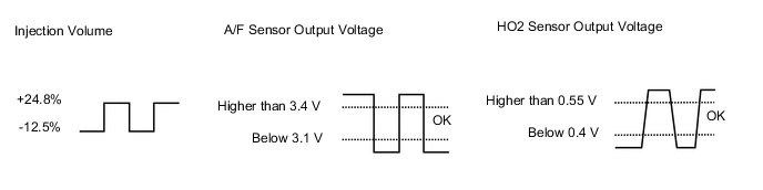
Read the output voltage from the air fuel ratio sensor when increasing and decreasing the fuel injection volume.
Standard Tester Display Specified Condition Control the Injection Volume (24.8%) Air fuel ratio sensor output voltage is below 3.1 V Control the Injection Volume (-12.5%) Air fuel ratio sensor output voltage is higher than 3.4 V Result Result Proceed to Abnormal A Normal B Tech Tips
-
The air fuel ratio sensor has an output delay of a few seconds and the heated oxygen sensor has a maximum output delay of approximately 20 seconds.
-
Even if the results are normal, the air fuel ratio sensor may have been malfunctioning. Continue this inspection procedure until step 24, and if there are no problems with other parts, replace the air fuel ratio sensor (refer to step 58).
-
B
READ FREEZE FRAME DATA Click here
A
-
-
CHECK HARNESS AND CONNECTOR (AIR FUEL RATIO SENSOR - BODY GROUND)
-
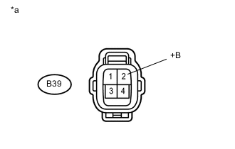
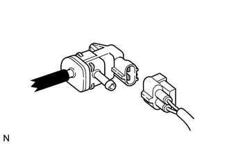
Text in Illustration *a Front view of wire harness connector
(to Air Fuel Ratio Sensor)
Disconnect the air fuel ratio sensor connector.
-
Turn the ignition switch to ON.
-
Measure the voltage according to the value(s) in the table below.
Standard Voltage Tester Connection Switch Condition Specified Condition B39-2 (+B) - Body ground Ignition switch ON 11 to 14 V Tech Tips
-
Jiggle the wire harness and connector to increase the likelihood of detecting malfunctions that do not always occur.
-
Make sure there is not an excessive amount of force applied to the wire harness.
-
-
Reconnect the air fuel sensor connector.
NG
CHECK POWER SOURCE CIRCUIT Click here
OK
-
-
CHECK HARNESS AND CONNECTOR (AIR FUEL RATIO SENSOR - ECM)
-
Disconnect the air fuel ratio sensor connector.
-
Disconnect the ECM connector.
-
Measure the resistance according to the value(s) in the table below.
Standard Resistance (Check for Open) Tester Connection Condition Specified Condition B39-1 (HA1A) - B23-23 (HA1A) Always Below 1 Ω B39-3 (A1A+) - B23-133 (A1A+) Always Below 1 Ω B39-4 (A1A-) - B23-134 (A1A-) Always Below 1 Ω Standard Resistance (Check for Short) Tester Connection Condition Specified Condition B39-1 (HA1A) or B23-23 (HA1A) - Body ground Always 10 kΩ or higher B39-3 (A1A+) or B23-133 (A1A+) - Body ground Always 10 kΩ or higher B39-4 (A1A-) or B23-134 (A1A-) - Body ground Always 10 kΩ or higher Result Result Proceed to Abnormal A Normal B Tech Tips
-
Jiggle the wire harness and connector to increase the likelihood of detecting malfunctions that do not always occur.
-
Make sure there is not an excessive amount of force applied to the wire harness.
-
-
Reconnect the ECM connector.
-
Reconnect the air fuel ratio sensor connector.
Tech Tips
Perform "Inspection After Repairs" after replacing the air fuel ratio sensor Click here.
A
REPAIR OR REPLACE HARNESS OR CONNECTOR
B
REPLACE AIR FUEL RATIO SENSOR Click here
-
-
READ FREEZE FRAME DATA
-
Connect the intelligent tester to the DLC3.
-
Turn the ignition switch to ON.
-
Using the intelligent tester, confirm the vehicle conditions recorded in the freeze frame data which were present when the DTC was stored Click here.
Result Freeze Frame Data Item for DTC P1605 Result Proceed to Ambient Temperature, Initial Engine Coolant Temp, Initial Intake Air Temp Difference in temperature between each item is below 10°C (18°F)*1 A Difference in temperature between each item is 10°C (18°F) or more*2 B Tech Tips
-
*1: A long time had elapsed after stopping the engine.
-
*2: A long time had not elapsed after stopping the engine.
-
B
READ FREEZE FRAME DATA Click here
A
-
-
READ FREEZE FRAME DATA
-
Connect the intelligent tester to the DLC3.
-
Turn the ignition switch to ON.
-
Using the intelligent tester, confirm the vehicle conditions recorded in the freeze frame data which were present when the DTC was stored Click here.
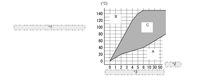
*1 Engine Coolant Temperature Increase after Engine Start (Engine Coolant Temperature - Engine Coolant Temperature at Engine Start) *2 (Minutes) *3 Time Elapsed after Engine Start Result Freeze Frame Data Item for DTC P1605 Result Suspected Area Proceed to Coolant Temp, Engine Run Time, Initial Engine Coolant Temp Range A
-
Engine coolant temperature sensor
-
Thermostat
A Range B Engine coolant temperature sensor B Range C - C Tech Tips
This step is not directly related to engine stall.
-
B
INSPECT ENGINE COOLANT TEMPERATURE SENSOR Click here
C
READ FREEZE FRAME DATA Click here
A
-
-
INSPECT THERMOSTAT
For the thermostat inspection, refer to the following procedures Click here.
Result Result Proceed to Abnormal A Normal B Tech Tips
This step is not directly related to engine stall.
A
REPLACE THERMOSTAT Click here
B
INSPECT ENGINE COOLANT TEMPERATURE SENSOR Click here
-
READ FREEZE FRAME DATA
-
Connect the intelligent tester to the DLC3.
-
Turn the ignition switch to ON.
-
Using the intelligent tester, confirm the vehicle conditions recorded in the freeze frame data which were present when the DTC was stored Click here.
Result Freeze Frame Data Item for DTC P1605 Result Suspected Area Proceed to Coolant Temp 120°C (248°F) or more Engine coolant temperature sensor A Coolant Temp, Ambient Temperature Engine coolant temperature is lower than outside temperature by 15°C (27°F) or more Engine coolant temperature sensor Both freeze frame data items listed above Values are other than above - B
B
READ FREEZE FRAME DATA Click here
A
-
-
INSPECT ENGINE COOLANT TEMPERATURE SENSOR
For the engine coolant temperature sensor inspection, refer to the following procedures Click here.
Result Result Proceed to Abnormal A Normal B Tech Tips
Even if the results are normal, the engine coolant temperature sensor may have been malfunctioning. Continue this inspection procedure until step 24, and if there are no problems with other parts, replace the engine coolant temperature sensor (refer to step 58).
A
REPLACE ENGINE COOLANT TEMPERATURE SENSOR Click here
B
-
READ FREEZE FRAME DATA
-
Connect the intelligent tester to the DLC3.
-
Turn the ignition switch to ON.
-
Using the intelligent tester, confirm the vehicle conditions recorded in the freeze frame data which were present when the DTC was stored Click here.
Result Freeze Frame Data Item for DTC P1605 Result Suspected Area Proceed to EVAP (Purge) VSV At least 1 of the 5 sets of freeze frame data 0% Purge valve A All 5 sets of freeze frame data are 0% - B Tech Tips
If the purge valve is stuck closed, air-fuel ratio compensation by the purge is incorrectly adjusted, and then the air-fuel ratio becomes lean and the engine may stall.
B
PERFORM ACTIVE TEST USING INTELLIGENT TESTER (CONTROL THE FUEL PUMP/SPEED) Click here
A
-
-
PERFORM ACTIVE TEST USING INTELLIGENT TESTER (ACTIVATE THE VSV FOR EVAP CONTROL)
-
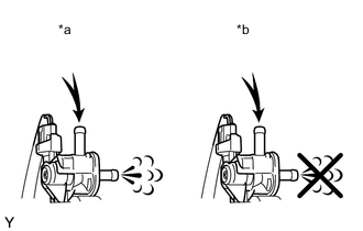
Text in Illustration *a VSV is on *b VSV is off Connect an intelligent tester to the DLC3.
-
Disconnect the purge valve hose (charcoal canister side) from the purge valve.
-
Start the engine.
-
Turn the tester on.
-
Enter the following menus: Powertrain / Engine and ECT / Active Test / Activate the VSV for Evap Control.
-
When the purge valve is operated using the intelligent tester, check whether the port of the purge valve applies suction to your finger.
OK Tester Operation Specified Condition VSV ON Purge valve port applies suction to finger VSV OFF Purge valve port applies no suction to finger Result Result Proceed to Abnormal A Normal B Tech Tips
-
Jiggle the wire harness and connector to increase the likelihood of detecting malfunctions that do not always occur.
-
Even if the results are normal, the purge valve may have been malfunctioning. Continue this inspection procedure until step 24, and if there are no problems with other parts, replace the purge valve (refer to step 58).
-
-
Reconnect the purge valve hose.
B
PERFORM ACTIVE TEST USING INTELLIGENT TESTER (CONTROL THE FUEL PUMP/SPEED) Click here
A
-
-
INSPECT PURGE VALVE
-
Inspect the purge valve Click here.
NG
REPLACE PURGE VALVE Click here
OK
-
-
CHECK HARNESS AND CONNECTOR (POWER SOURCE)
-
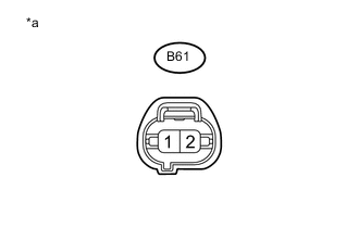
Text in Illustration *a Front view of wire harness connector
(to Purge Valve)
Disconnect the purge valve connector.
-
Turn the ignition switch to ON.
-
Measure the voltage according to the value(s) in the table below.
Standard Voltage Tester Connection Switch Condition Specified Condition B61-1 - Body ground Ignition switch ON 11 to 14 V Tech Tips
-
Jiggle the wire harness and connector to increase the likelihood of detecting malfunctions that do not always occur.
-
Make sure there is not an excessive amount of force applied to the wire harness.
-
-
Reconnect the purge valve connector.
NG
CHECK POWER SOURCE CIRCUIT Click here
OK
-
-
CHECK HARNESS AND CONNECTOR (PURGE VALVE - ECM)
-
Disconnect the purge valve connector.
-
Disconnect the ECM connector.
-
Measure the resistance according to the value(s) in the table below.
Standard Resistance (Check for Open) Tester Connection Condition Specified Condition B61-2 - B23-76 (PRG) Always Below 1 Ω Standard Resistance (Check for Short) Tester Connection Condition Specified Condition B61-2 or B23-76 (PRG) - Body ground Always 10 kΩ or higher Tech Tips
-
Jiggle the wire harness and connector to increase the likelihood of detecting malfunctions that do not always occur.
-
Make sure there is not an excessive amount of force applied to the wire harness.
-
-
Reconnect the purge valve connector.
-
Reconnect the ECM connector.
OK
REPLACE ECM Click here
NG
REPAIR OR REPLACE HARNESS OR CONNECTOR
-
-
PERFORM ACTIVE TEST USING INTELLIGENT TESTER (CONTROL THE FUEL PUMP/SPEED)
-
Connect an intelligent tester to the DLC3.
-
Turn the ignition switch to ON.
-
Turn the tester on.
-
Enter the following menus: Powertrain / Engine and ECT / Active Test / Control the Fuel Pump/Speed.
-
Check whether the fuel pump operating sound occurs when performing the Active Test on the tester.
OK Control the Fuel Pump / Speed Specified Condition ON Operating sound heard OFF Operating sound not head Result Result Proceed to NG A OK B Tech Tips
-
Jiggle the wire harness and connector to increase the likelihood of detecting malfunctions that do not always occur.
-
While performing the Active Test, make sure that there is no fuel leakage from the pipes, no signs that fuel has leaked, and no fuel smell.
-
If the fuel pump operating noise is abnormal, proceed to step 23.
-
B
CHECK FUEL SYSTEM Click here
A
-
-
INSPECT FUEL PUMP
-
Inspect the fuel pump Click here.
OK
CHECK FUEL PUMP CONTROL SYSTEM Click here
NG
REPLACE FUEL PUMP Click here
-
-
CHECK FUEL SYSTEM
-
Check for foreign matter such as iron particles around the fuel pump (fuel pump, fuel pump filter and inside the fuel tank), and for signs that the fuel pump was stuck.
Result Result Proceed to There is foreign matter or signs that fuel pump was stuck A There is no foreign matter and no signs that fuel pump was stuck B Tech Tips
If there is foreign matter such as iron particles on the fuel pump, fuel filter or fuel tank, remove the foreign matter.
A
CHECK FUEL SYSTEM Click here
B
REPLACE MALFUNCTIONING PARTS Click here
-
-
READ FREEZE FRAME DATA
-
Connect the intelligent tester to the DLC3.
-
Turn the ignition switch to ON.
-
Using the intelligent tester, confirm the vehicle conditions recorded in the freeze frame data which were present when the DTC was stored Click here.
Result Freeze Frame Data Item for DTC P1605 Result Suspected Area Proceed to Calculate Load 110% or more of the current value of the vehicle*1 Mass air flow meter A AFS Voltage B1S1 Below 3.3 V*2
-
Air fuel ratio sensor
-
Harness and connector
-
Actual air fuel ratio abnormal
B Both freeze frame data items listed above Values are other than above - C Tech Tips
-
Try to operate the vehicle under the conditions recorded in the freeze frame data which were present when the malfunction occurred. Confirm the data at this time and the data when the engine is idling (engine warmed up, no load, and shift lever in D or N) and compare these data with the freeze frame data.
-
*1: If the mass air flow meter is malfunctioning and incorrectly measures the intake air volume to be higher than the actual intake air volume, the freeze frame data will show a high engine load value.
-
*2: As the air fuel ratio sensor output is low before the sensor warms up, the value at that time cannot be used for diagnosis. If the air fuel ratio sensor is malfunctioning and constantly outputs a value indicating the air-fuel ratio is rich, the actual air-fuel ratio will become lean and the engine may stall.
-
B
PERFORM ACTIVE TEST USING INTELLIGENT TESTER (CONTROL INJECTION VOLUME) Click here
C
READ FREEZE FRAME DATA Click here
A
-
-
INSPECT MASS AIR FLOW METER
-
Remove the mass air flow meter.
-
Check for foreign matter in the air flow passage of the mass air flow meter.
Result Result Proceed to Visible foreign matter is present A Visible foreign matter is not present B Tech Tips
-
Even if the results are normal, the mass air flow meter may have been malfunctioning. Continue this inspection procedure until step 34, and if there are no problems with other parts, replace the mass air flow meter (refer to step 58).
-
Perform "Inspection After Repairs" after replacing the mass air flow meter Click here.
-
A
REPLACE MASS AIR FLOW METER Click here
B
READ FREEZE FRAME DATA Click here
-
-
PERFORM ACTIVE TEST USING INTELLIGENT TESTER (CONTROL INJECTION VOLUME)
-
Connect the intelligent tester to the DLC3.
-
Turn the ignition switch to ON.
-
Start the engine, turn off all accessory switches and warm up the engine until the engine coolant temperature stabilizes.
-
Idle the engine.
-
Turn the tester on.
-
Enter the following menus: Powertrain / Engine and ECT / Active Test / Control the injection volume.
-
Read the output voltage from the air fuel ratio sensor when increasing and decreasing the fuel injection volume.
Standard Tester Display Specified Condition Control the Injection Volume (24.8%) Air fuel ratio sensor output voltage is below 3.1 V Control the Injection Volume (-12.5%) Air fuel ratio sensor output voltage is higher than 3.4 V Result Result Proceed to Abnormal A Normal B Tech Tips
-
The air fuel ratio sensor has an output delay of a few seconds and the heated oxygen sensor has a maximum output delay of approximately 20 seconds.
-
Even if the results are normal, the air fuel ratio sensor may have been malfunctioning. Continue this inspection procedure until step 34, and if there are no problems with other parts, replace the air fuel ratio sensor (refer to step 58).
-
B
READ FREEZE FRAME DATA Click here
A
-
-
CHECK HARNESS AND CONNECTOR (AIR FUEL RATIO SENSOR - BODY GROUND)
-
Text in Illustration *a Front view of wire harness connector
(to Air Fuel Ratio Sensor)
Disconnect the air fuel ratio sensor connector.
-
Turn the ignition switch to ON.
-
Measure the voltage according to the value(s) in the table below.
Standard Voltage Tester Connection Switch Condition Specified Condition B39-2 (+B) - Body ground Ignition switch ON 11 to 14 V Tech Tips
-
Jiggle the wire harness and connector to increase the likelihood of detecting malfunctions that do not always occur.
-
Make sure there is not an excessive amount of force applied to the wire harness.
-
-
Reconnect the air fuel sensor connector.
NG
CHECK POWER SOURCE CIRCUIT Click here
OK
-
-
CHECK HARNESS AND CONNECTOR (AIR FUEL RATIO SENSOR - ECM)
-
Disconnect the air fuel ratio sensor connector.
-
Disconnect the ECM connector.
-
Measure the resistance according to the value(s) in the table below.
Standard Resistance (Check for Open) Tester Connection Condition Specified Condition B39-1 (HA1A) - B23-23 (HA1A) Always Below 1 Ω B39-3 (A1A+) - B23-133 (A1A+) Always Below 1 Ω B39-4 (A1A-) - B23-134 (A1A-) Always Below 1 Ω Standard Resistance (Check for Short) Tester Connection Condition Specified Condition B39-1 (HA1A) or B23-23 (HA1A) - Body ground Always 10 kΩ or higher B39-3 (A1A+) or B23-133 (A1A+) - Body ground Always 10 kΩ or higher B39-4 (A1A-) or B23-134 (A1A-) - Body ground Always 10 kΩ or higher Tech Tips
-
Jiggle the wire harness and connector to increase the likelihood of detecting malfunctions that do not always occur.
-
Make sure there is not an excessive amount of force applied to the wire harness.
-
-
Reconnect the ECM connector.
-
Reconnect the air fuel ratio sensor connector.
Tech Tips
Perform "Inspection After Repairs" after replacing the air fuel ratio sensor Click here.
OK
REPLACE AIR FUEL RATIO SENSOR Click here
NG
REPAIR OR REPLACE HARNESS OR CONNECTOR
-
-
READ FREEZE FRAME DATA
-
Connect the intelligent tester to the DLC3.
-
Turn the ignition switch to ON.
-
Using the intelligent tester, confirm the vehicle conditions recorded in the freeze frame data which were present when the DTC was stored Click here.
Result Freeze Frame Data Item for DTC P1605 Result Proceed to Ambient Temperature, Initial Engine Coolant Temp, Initial Intake Air Temp Difference in temperature between each item is below 10°C (18°F)*1 A Difference in temperature between each item is 10°C (18°F) or more*2 B Tech Tips
-
*1: A long time had elapsed after stopping the engine.
-
*2: A long time had not elapsed after stopping the engine.
-
B
READ FREEZE FRAME DATA Click here
A
-
-
READ FREEZE FRAME DATA
-
Connect the intelligent tester to the DLC3.
-
Turn the ignition switch to ON.
-
Using the intelligent tester, confirm the vehicle conditions present when the DTC was stored which are recorded in the freeze frame data Click here.
*1 Engine Coolant Temperature Increase after Engine Start (Engine Coolant Temperature - Engine Coolant Temperature at Engine Start) *2 (Minutes) *3 Time Elapsed after Engine Start Result Freeze Frame Data Item for DTC P1605 Result Suspected Area Proceed to Coolant Temp, Engine Run Time, Initial Engine Coolant Temp Range A
-
Engine coolant temperature sensor
-
Thermostat
A Range B Engine coolant temperature sensor B Range C - C Tech Tips
This step is not directly related to engine stall.
-
B
INSPECT ENGINE COOLANT TEMPERATURE SENSOR Click here
C
CLEAR DTC Click here
A
-
-
INSPECT THERMOSTAT
For the thermostat inspection, refer to the following procedures Click here.
Result Result Proceed to Abnormal A Normal B Tech Tips
This step is not directly related to engine stall.
A
REPLACE THERMOSTAT Click here
B
INSPECT ENGINE COOLANT TEMPERATURE SENSOR Click here
-
READ FREEZE FRAME DATA
-
Connect the intelligent tester to the DLC3.
-
Turn the ignition switch to ON.
-
Using the intelligent tester, confirm the vehicle conditions recorded in the freeze frame data which were present when the DTC was stored Click here.
Result Freeze Frame Data Item for DTC P1605 Result Suspected Area Proceed to Coolant Temp 120°C (248°F) or more Engine coolant temperature sensor A Coolant Temp, Ambient Temperature Engine coolant temperature is lower than outside temperature by 15°C (27°F) or more Engine coolant temperature sensor Both freeze frame data items listed above Values are other than above - B
B
CLEAR DTC Click here
A
-
-
INSPECT ENGINE COOLANT TEMPERATURE SENSOR
For the engine coolant temperature sensor inspection, refer to the following procedures Click here.
Result Result Proceed to Abnormal A Normal B Tech Tips
Even if the results are normal, the engine coolant temperature sensor may have been malfunctioning. If there are no problems with other parts, replace the engine coolant temperature sensor (refer to step 58).
A
REPLACE ENGINE COOLANT TEMPERATURE SENSOR Click here
B
REPLACE MALFUNCTIONING PARTS Click here
-
READ FREEZE FRAME DATA
-
Connect the intelligent tester to the DLC3.
-
Turn the ignition switch to ON.
-
Using the intelligent tester, confirm the vehicle conditions recorded in the freeze frame data which were present when the DTC was stored Click here.
Result Freeze Frame Data Item for DTC P1605 Result Suspected Area Proceed to Total of ISC Learning Value and ISC Feedback Value Below 80% of the current value of the vehicle*1 Throttle with motor body assembly A 120% or more of the current value of the vehicle*2 B From 80 to 120% of the current value of the vehicle - C Tech Tips
-
Try to operate the vehicle under the conditions recorded in the freeze frame data which were present when the malfunction occurred. Confirm the data at this time and the data when the engine is idling (engine warmed up, no load, and shift lever in D or N) and compare these data with the freeze frame data.
-
*1: If the throttle with motor body assembly has a temporary problem in which it cannot fully close, the intake air volume and engine speed increase. As a result, the ISC learning amount becomes less than the standard. At this time, if the Throttle with motor body assembly returns to normal and fully closes, the intake air volume will be insufficient and the engine may stall.
-
*2: If carbon accumulates on the Throttle with motor body assembly and the intake air volume decreases, the ISC learning amount is increased to maintain the idling speed. If this situation continues, the ISC learning amount reaches the upper limit, the idling speed cannot be maintained causing idling to become unstable, and the engine may stall.
-
B
INSPECT THROTTLE WITH MOTOR BODY ASSEMBLY Click here
C
PERFORM ACTIVE TEST USING INTELLIGENT TESTER (CONTROL THE VVT SYSTEM) Click here
A
-
-
INSPECT THROTTLE WITH MOTOR BODY ASSEMBLY
-
Check for foreign matter and signs that the Throttle with motor body assembly was stuck, and also check that the valve and shaft move smoothly during operation.
Result Result Proceed to Abnormal A Normal B Tech Tips
-
Even if the results are normal, the Throttle with motor body assembly may have been malfunctioning. Continue this inspection procedure until step 43, and if there are no problems with other parts, replace the Throttle with motor body assembly (refer to step 58).
-
Perform "Inspection After Repairs" after replacing the throttle with motor body assembly Click here.
-
A
REPLACE THROTTLE WITH MOTOR BODY ASSEMBLY Click here
B
PERFORM ACTIVE TEST USING INTELLIGENT TESTER (CONTROL THE VVT SYSTEM) Click here
-
-
INSPECT THROTTLE WITH MOTOR BODY ASSEMBLY
-
Check if carbon is in the air flow passage.
Result Result Proceed to Carbon in passage A No carbon in passage B Tech Tips
-
Even if the results are normal, the Throttle with motor body assembly may have been malfunctioning. Continue this inspection procedure until step 43, and if there are no problems with other parts, replace the Throttle with motor body assembly (refer to step 58).
-
Perform "Inspection After Repairs" after replacing the throttle with motor body assembly Click here.
-
A
REPLACE THROTTLE WITH MOTOR BODY ASSEMBLY Click here
B
-
-
PERFORM ACTIVE TEST USING INTELLIGENT TESTER (CONTROL THE VVT SYSTEM)
-
Connect the intelligent tester to the DLC3.
-
Turn the intelligent tester on.
-
Warm up the engine.
-
Turn the tester on.
-
Enter the following menus: Powertrain / Engine and ECT / Active Test / Control the VVT system.
-
Check the engine speed while operating the Oil Control Valve (OCV) using the intelligent tester.
OK Tester Operation Specified Condition OFF Normal engine speed ON Soon after OCV switched from OFF to ON, engine idles roughly or stalls Tech Tips
-
Jiggle the wire harness and connector to increase the likelihood of detecting malfunctions that do not always occur.
-
When the results of the inspection using the Active Test are normal but the valve operating noise is abnormal, check the valve for any signs of problems.
-
If the camshaft timing oil control valve is stuck ON, the valve overlap increases and combustion worsens due to the internal EGR which may cause rough idle or cause the engine to stall.
-
NG
REPLACE CAMSHAFT TIMING OIL CONTROL VALVE ASSEMBLY Click here
OK
-
-
PERFORM ACTIVE TEST USING INTELLIGENT TESTER (CONTROL THE EGR STEP POSITION)
-
Check the EGR valve assembly operation.
-
Connect the intelligent tester to the DLC3.
-
Turn the ignition switch to ON.
-
Turn the tester on.
-
Start the engine and warm it up until the engine coolant temperature reaches 75°C (167°F) or more.
Tech Tips
The A/C switch and all accessory switches should be off.
-
Enter the following menus: Powertrain / Engine and ECT / Active Test / Control the EGR Step Position.
-
Check the engine idling condition in the Data List while performing the Active Test.
OK EGR Step Position
(Active Test)
Specified Condition 0 Steps Steady idling 0 to 30 Steps Idling changes from steady to rough idling Tech Tips
-
Do not leave the EGR valve open for 10 seconds or more during the Active Test.
-
Be sure to return the EGR valve to step 0 when the Active Test is completed.
Result Result Proceed to Outside of standard range A Within standard range B -
-
B
READ FREEZE FRAME DATA Click here
A
-
-
INSPECT EGR VALVE ASSEMBLY
-
Remove the EGR valve assembly Click here.
-
Check if the EGR valve assembly is stuck open.
OK EGR valve is tightly closed (It is not stuck open). -
Reinstall the EGR valve assembly Click here.
NG
REPLACE EGR VALVE ASSEMBLY Click here
OK
-
-
READ FREEZE FRAME DATA
-
Connect the intelligent tester to the DLC3.
-
Turn the ignition switch to ON.
-
Using the intelligent tester, confirm the vehicle conditions recorded in the freeze frame data which were present when the DTC was stored Click here.
Result Freeze Frame Data Item for DTC P1605 Suspected Area Proceed to IGN Advance Knock Correct Learn Value Differs from the current value of the vehicle by 10° or more Below 3°
-
Engine coolant temperature sensor
-
Mass air flow meter
-
Knock sensor
A 3° or more - Differs from the current value of the vehicle by less than 10° - - B Tech Tips
-
Try to operate the vehicle under the conditions recorded in the freeze frame data which were present when the malfunction occurred. Confirm the data at this time and the data when the engine is idling (engine warmed up, no load, and shift lever in D or N) and compare these data with the freeze frame data.
-
Even if the results are normal, the knock sensor may have been malfunctioning. If there are no problems with other parts, replace the knock sensor (refer to step 58).
-
B
REPLACE MALFUNCTIONING PARTS Click here
A
-
-
INSPECT ENGINE COOLANT TEMPERATURE SENSOR
For the engine coolant temperature inspection, refer to the following procedures Click here.
NG
REPLACE ENGINE COOLANT TEMPERATURE SENSOR Click here
OK
-
INSPECT MASS AIR FLOW METER
-
Inspect the mass air flow meter Click here.
Tech Tips
-
If the intake air temperature sent to the ECM is higher than the standard due to the mass air flow meter (intake air temperature sensor) malfunctioning, the ignition timing may become delayed.
-
Perform "Inspection After Repairs" after replacing the mass air flow meter Click here.
-
OK
REPLACE KNOCK SENSOR Click here
NG
REPLACE MASS AIR FLOW METER Click here
-
-
CHECK HARNESS AND CONNECTOR (FUEL INJECTOR ASSEMBLY - POWER SOURCE VOLTAGE)
-
Text in Illustration *a Front view of wire harness connector
(to Fuel Injector Assembly)
Disconnect the fuel injector assembly connector.
-
Turn the ignition switch to ON.
-
Measure the voltage according to the value(s) in the table below.
Standard Voltage Tester Connection Switch Condition Specified Condition B5-1 - Body ground Ignition switch ON 11 to 14 V B7-1 - Body ground Ignition switch ON 11 to 14 V B9-1 - Body ground Ignition switch ON 11 to 14 V B11-1 - Body ground Ignition switch ON 11 to 14 V Tech Tips
-
Jiggle the wire harness and connector to increase the likelihood of detecting malfunctions that do not always occur.
-
Make sure there is not an excessive amount of force applied to the wire harness.
-
A rapid decrease in engine speed may have been caused by a malfunction in all or multiple cylinders. (There may be an electrical malfunction in the wiring shared by all the cylinders.)
-
-
Reconnect the fuel injector assembly connector.
NG
CHECK FUEL INJECTOR CIRCUIT Click here
OK
-
-
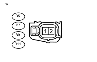
CHECK HARNESS AND CONNECTOR (IGNITION COIL POWER SOURCE VOLTAGE)
-
Text in Illustration *a Front view of wire harness connector
(to Ignition Coil Assembly)
Disconnect the ignition coil assembly connectors.
-
Turn the ignition switch to ON.
-
Measure the voltage according to the value(s) in the table below.
Standard Voltage Tester Connection Switch Condition Specified Condition B13-1 (+B) - B13-4 (GND) Ignition switch ON 11 to 14 V B15-1 (+B) - B15-4 (GND) Ignition switch ON 11 to 14 V B17-1 (+B) - B17-4 (GND) Ignition switch ON 11 to 14 V B19-1 (+B) - B19-4 (GND) Ignition switch ON 11 to 14 V Tech Tips
-
Jiggle the wire harness and connector to increase the likelihood of detecting malfunctions that do not always occur.
-
Make sure there is not an excessive amount of force applied to the wire harness.
-
A rapid decrease in engine speed may have been caused by a malfunction in all or multiple cylinders. (There may be an electrical malfunction in the wiring shared by all the cylinders.)
-
-
Reconnect the ignition coil assembly connectors.
NG
CHECK POWER SOURCE CIRCUIT Click here
OK
-
-
READ FREEZE FRAME DATA
-
Connect the intelligent tester to the DLC3.
-
Turn the ignition switch to ON.
-
Using the intelligent tester, confirm the vehicle conditions recorded in the freeze frame data which were present when the DTC was stored Click here.
Result Freeze Frame Data Item Result Suspected Area Proceed to Idle Spark Advn Ctrl (#1 to #4) At least one cylinder shows a value of 4° or more
-
Fuel injector system
-
Ignition coil system
A All cylinders show a value of less than 4° - B -
B
READ FREEZE FRAME DATA Click here
A
-
-
READ FREEZE FRAME DATA
-
Change the location of the ignition coil for the cylinder whose Idle Spark Advn Ctrl (#1 to #4) was 4° or more in step 46.
-
Connect the intelligent tester to the DLC3.
-
Turn the ignition switch to ON.
-
Turn the tester on.
-
Enter the following menus: Powertrain / Engine and ECT / Data List / Idle Spark Advn Ctrl (#1 to #4).
Result Result Proceed to Same as result in step 46 A Different from result in step 46 B Tech Tips
Jiggle the wire harness and connector to increase the likelihood of detecting malfunctions that do not always occur.
B
REPLACE IGNITION COIL ASSEMBLY Click here
A
-
-
READ FREEZE FRAME DATA
-
Connect the intelligent tester to the DLC3.
-
Turn the ignition switch to ON.
-
Using the intelligent tester, confirm the vehicle conditions recorded in the freeze frame data which were present when the DTC was stored Click here.
Result Freeze Frame Data Item for DTC P1605 Suspected Area Proceed to A/C Signal Air Conditioner FB Val Power Steering Signal Record A/C Signal display changes from OFF to ON*1 Value is shown - A/C system A*2
B*3
Value is 0 L/s Does not change from OFF - C Changes from OFF to ON Power steering system A/C Signal display does not change from OFF*1 - Changes from OFF to ON Does not change from OFF -
-
*1: Check not only the ON/ OFF state of the air conditioner but also the change in air conditioner load.
-
*2: for Automatic Air Conditioning
-
*3: for Manual Air Conditioning
Tech Tips
-
Try to operate the vehicle under the conditions recorded in the freeze frame data which were present when the malfunction occurred. Confirm the data at this time and the data when the engine is idling (engine warmed up, no load, and shift lever in D or N) and compare these data with the freeze frame data.
-
The normal value for ISC learning amount is engine displacement (liters) x 0.9.
-
Even if the results are normal, the power steering system may have been malfunctioning. Continue this inspection procedure until step 52, and if there are no problems with other parts, inspect the power steering system (refer to step 58).
-
A
CHECK AIR CONDITIONING SYSTEM (FOR AUTOMATIC AIR CONDITIONING) Click here
B
CHECK AIR CONDITIONING SYSTEM (FOR MANUAL AIR CONDITIONING) Click here
C
-
-
READ FREEZE FRAME DATA
-
Connect the intelligent tester to the DLC3.
-
Turn the ignition switch to ON.
-
Using the intelligent tester, confirm the vehicle conditions recorded in the freeze frame data which were present when the DTC was stored Click here.
Result Freeze Frame Data Item for DTC P1605 Suspected Area Proceed to Electrical Load Signal, Electrical Load compensation amount Electrical Load compensation amount Difference between Engine Speed and Turbine Speed Vehicle Speed Electrical Load Signal display changes from OFF to ON*1, or Value displayed for Electric Load Feedback Val increases*1 Value displayed for Electric Load Val changes - - Electrical load signal circuit A Value displayed for Electric Load Val does not change At least 1 of the 5 sets of freeze frame data is below 100 rpm Below 18 km/h CVT system B 18 km/h or more - C All 5 sets of freeze frame data are 100 rpm or more - - C Electrical Load Signal display does not change from OFF, or Value displayed for Electric Load Feed back Val does not increase - At least 1 of the 5 sets of freeze frame data is below 100 rpm Below 18 km/h CVT system B 18 km/h or more - C All 5 sets of freeze frame data are 100 rpm or more - - C
-
*1: If the Electrical Load Signal display changes from OFF to ON or the "Electric Load Feedback Val" increases, it probably is a malfunction due to a change in electrical load. Check the generator and ECM.
Tech Tips
-
The normal value for the ISC learning amount is engine displacement (liters) x 0.9.
-
Even if the results are normal, the electrical load signal system and/or the CVT system may have been malfunctioning. Continue this inspection procedure until step 50, and if there are no problems with other parts, inspect the electrical load system and/or the CVT system (refer to step 58).
-
A
CHECK GENERATOR CIRCUIT Click here
B
CHECK CVT SYSTEM
C
-
-
READ FREEZE FRAME DATA
-
Connect the intelligent tester to the DLC3.
-
Turn the ignition switch to ON.
-
Using the intelligent tester, confirm the vehicle conditions recorded in the freeze frame data which were present when the DTC was stored Click here.
Result Freeze Frame Data Item for DTC P1605 Suspected Area Proceed to P position or N position Park/Neutral position switch At least 1 of the 5 sets of freeze frame data is OFF In D or R, NSW is ON Neutral start switch system A In D or R, NSW is OFF CVT system B All 5 sets of freeze frame data are ON - - C Tech Tips
Even if the results are normal, the neutral start switch system and/or CVT system may have been malfunctioning. If there are no problems with other parts, inspect the neutral start switch system and/or CVT system (refer to step 58).
A
INSPECT PARK/NEUTRAL POSITION SWITCH ASSEMBLY Click here
B
CHECK CVT SYSTEM
C
REPLACE MALFUNCTIONING PARTS Click here
-
-
READ FREEZE FRAME DATA
-
Connect the intelligent tester to the DLC3.
-
Turn the ignition switch to ON.
-
Using the intelligent tester, confirm the vehicle conditions recorded in the freeze frame data which were present when the DTC was stored Click here.
Result Freeze Frame Data Item Result Suspected Area Proceed to Calculate Load, Throttle Sensor Position Calculate Load decreases while Throttle Sensor Position increases Mass air flow meter A Calculate Load does not decrease while Throttle Sensor Position increases - B
B
CHECK HARNESS AND CONNECTOR (FUEL INJECTOR POWER SOURCE VOLTAGE) Click here
A
-
-
INSPECT MASS AIR FLOW METER
-
Remove the mass air flow meter Click here.
-
Check for foreign matter in the air flow passage of the mass air flow meter.
Result Result Proceed to Visible foreign matter is present A Visible foreign matter is not present B -
Install the mass air flow meter Click here.
Tech Tips
-
Even if the results are normal, the mass air flow meter may have been malfunctioning. Continue this inspection procedure until step 57, and if there are no problems with other parts, replace the mass air flow meter (refer to step 58).
-
Perform "Inspection After Repairs" after replacing the mass air flow meter Click here.
-
A
REPLACE MASS AIR FLOW METER Click here
B
-
-
CHECK HARNESS AND CONNECTOR (FUEL INJECTOR POWER SOURCE VOLTAGE)
-
Text in Illustration *a Front view of wire harness connector
(to Fuel Injector Assembly)
Disconnect the fuel injector assembly connector.
-
Turn the ignition switch to ON.
-
Measure the voltage according to the value(s) in the table below.
Standard Voltage Tester Connection Switch Condition Specified Condition B5-1 - Body ground Ignition switch ON 11 to 14 V B7-1 - Body ground Ignition switch ON 11 to 14 V B9-1 - Body ground Ignition switch ON 11 to 14 V B11-1 - Body ground Ignition switch ON 11 to 14 V Tech Tips
-
Jiggle the wire harness and connector to increase the likelihood of detecting malfunctions that do not always occur.
-
Make sure there is not an excessive amount of force applied to the wire harness.
-
A rapid decrease in engine speed may have been caused by a malfunction in all or multiple cylinders. (There may be an electrical malfunction in the wiring shared by all the cylinders.)
-
-
Reconnect the fuel injector assembly connector.
NG
CHECK POWER SOURCE CIRCUIT Click here
OK
-
-
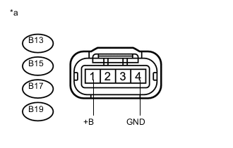
CHECK HARNESS AND CONNECTOR (IGNITION COIL POWER SOURCE VOLTAGE)
-
Text in Illustration *a Front view of wire harness connector
(to Ignition Coil Assembly)
Disconnect the ignition coil assembly connectors.
-
Turn the ignition switch to ON.
-
Measure the voltage according to the value(s) in the table below.
Standard Voltage Tester Connection Switch Condition Specified Condition B13-1 (+B) - B13-4 (GND) Ignition switch ON 11 to 14 V B15-1 (+B) - B15-4 (GND) Ignition switch ON 11 to 14 V B17-1 (+B) - B17-4 (GND) Ignition switch ON 11 to 14 V B19-1 (+B) - B19-4 (GND) Ignition switch ON 11 to 14 V Tech Tips
-
Jiggle the wire harness and connector to increase the likelihood of detecting malfunctions that do not always occur.
-
Make sure there is not an excessive amount of force applied to the wire harness.
-
A rapid decrease in engine speed may have been caused by a malfunction in all or multiple cylinders. (There may be an electrical malfunction in the wiring shared by all the cylinders.)
-
-
Reconnect the ignition coil assembly connectors.
NG
CHECK POWER SOURCE CIRCUIT Click here
OK
-
-
PERFORM ACTIVE TEST USING INTELLIGENT TESTER (CONTROL THE FUEL PUMP/SPEED)
-
Connect an intelligent tester to the DLC3.
-
Turn the ignition switch to ON.
-
Turn the tester on.
-
Enter the following menus: Powertrain / Engine and ECT / Active Test / Control the Fuel Pump/Speed.
-
Check whether the fuel pump operating sound occurs when performing the Active Test on the tester.
OK Control the Fuel Pump / Speed Specified Condition ON Operating sound heard OFF Operating sound not heard Result Result Proceed to NG A OK B Tech Tips
-
Jiggle the wire harness and connector to increase the likelihood of detecting malfunctions that do not always occur.
-
While performing the Active Test, make sure that there is no fuel leakage from the pipes, no signs that fuel has leaked, and no fuel smell.
-
If the fuel pump operating noise is abnormal, proceed to step 56.
-
B
CHECK FUEL SYSTEM Click here
A
-
-
INSPECT FUEL PUMP
-
Inspect the fuel pump Click here.
OK
CHECK FUEL PUMP CONTROL SYSTEM Click here
NG
REPLACE FUEL PUMP Click here
-
-
CHECK FUEL SYSTEM
-
Check for foreign matter such as iron particles around the fuel pump (fuel pump, fuel pump filter, fuel tank), and for signs that the fuel pump was stuck.
Result Result Proceed to There is foreign matter or signs that fuel pump was stuck A There is no foreign matter and no signs that fuel pump was stuck B Tech Tips
If there is foreign matter such as iron particles on the fuel pump, fuel filter or fuel tank, remove the foreign matter.
A
REPAIR OR REPLACE FUEL SYSTEM Click here
B
-
-
REPLACE MALFUNCTIONING PARTS
-
If the malfunction could not be identified in steps 3 to 24, replace the part which is suspected to be malfunctioning according to the step where an inspection was performed.
Performed Step Inspection or Part to Replace Step 6 Brake booster replacement Step 8 Mass air flow meter replacement Step 9 Air fuel ratio sensor replacement Step 16 Engine coolant temperature sensor replacement Step 18 Purge valve replacement Step 24 Fuel pump replacement -
If the malfunction could not be identified in steps 25 to 34, replace the part which is suspected to be malfunctioning according to the step where an inspection was performed.
Performed Step Inspection or Part to Replace Step 26 Mass air flow meter replacement Step 27 Air fuel ratio sensor replacement Step 34 Engine coolant temperature sensor replacement -
If the malfunction could not be identified in steps 35 to 43, replace the part which is suspected to be malfunctioning according to the step where an inspection was performed.
Performed Step Inspection or Part to Replace Step 36, 37 Throttle with motor body assembly replacement Step 39, 40 EGR valve assembly replacement Step 41 Knock sensor replacement -
If the malfunction could not be identified in steps 44 to 50, inspect and repair the part which is suspected to be malfunctioning according to the step where an inspection was performed.
Performed Step Inspection or Part to Repair Step 48 A/C system inspection and repair
Power steering system inspection and repair
Step 49 CVT system inspection and repair
Electrical load system inspection and repair
Step 50 Neutral start switch system inspection and repair
CVT system inspection and repair
-
If the malfunction could not be identified in steps 51 to 57, replace the part which is suspected to be malfunctioning according to the step where an inspection was performed.
Performed Step Inspection or Part to Replace Step 52 Mass air flow meter replacement Tech Tips
Referring to the chart, inspect and repair or replace the part from the step where an inspection was performed.
NEXT
-
-
CLEAR DTC
-
Connect the intelligent tester to the DLC3.
-
Turn the ignition switch to ON.
-
Clear the DTCs Click here.
NEXT
-
-
PERFORM CONFIRMATION DRIVING PATTERN
-
Check if engine stall symptoms are present.
Tech Tips
If any engine stall symptoms are present, recheck for DTCs and freeze frame data and perform an inspection.
OK
END
NG
REPAIR OR REPLACE MALFUNCTIONING PARTS, COMPONENT AND AREA
-