SFI SYSTEM, Diagnostic DTC:P0724
| DTC Code | DTC Name |
|---|---|
| P0724 | Brake Switch "B" Circuit High |
DESCRIPTION
The purpose of this circuit is to prevent the engine from stalling when brakes are suddenly applied while driving with the lock-up torque converter clutch on.
When the brake pedal is depressed, this switch sends a signal to the ECM. Then the ECM cancels the operation of the lock-up clutch while braking is in progress.
| DTC No. | DTC Detection Condition | Trouble Area |
|---|---|---|
| P0724 | Stop light switch assembly remains ON even when vehicle repeats 5 cycles of STOP (less than 3 km/h [1.86 mph]) and GO (30 km/h [18.65 mph] or more) (2 trip detection logic) |
|
MONITOR DESCRIPTION
This DTC indicates that the stop light switch remains on. When the stop light switch remains on during GO and STOP driving, the ECM interprets this as a fault in the stop light switch. Then the MIL illuminates and the ECM stores the DTC. The vehicle must GO (30 km/h (18.63 mph) or more) and STOP (less than 3 km/h (1.86 mph)) 5 times for 2 driving cycles in order for the DTC to be stored.
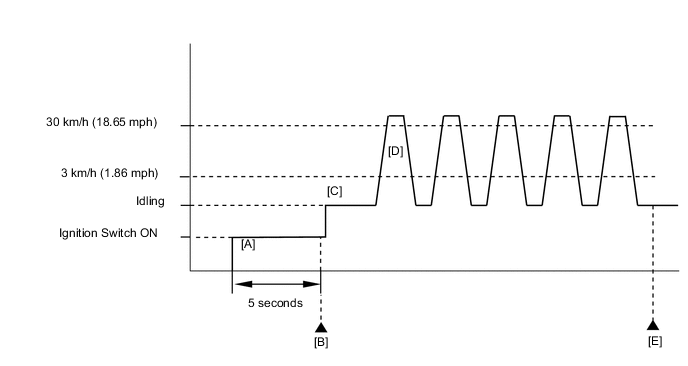
CONFIRMATION DRIVING PATTERN
-
Connect the intelligent tester to the DLC3.
-
Turn the ignition switch to ON and turn the intelligent tester on.
-
Clear the DTCs (even if no DTCs are stored, perform the clear DTC operation).
-
Turn the ignition switch off and wait for at least 30 seconds.
-
Turn the ignition switch to ON and turn the intelligent tester on [A].
-
Wait 5 seconds.
-
Enter the following menus: Powertrain / Engine and ECT / DTC [B].
-
Read the pending DTCs.
Tech Tips
-
If a pending DTC is output, the system is malfunctioning.
-
If a pending DTC is not output, perform the following procedure.
-
-
Enter the following menus: Powertrain / Engine and ECT / Utility / All Readiness.
-
Input the DTC: P0724.
-
Check the DTC judgment result.
Intelligent tester Display Description NORMAL
-
DTC judgment completed
-
System normal
ABNORMAL
-
DTC judgment completed
-
System abnormal
INCOMPLETE
-
DTC judgment not completed
-
Perform driving pattern after confirming DTC enabling conditions
UNKNOWN
-
Unable to perform DTC judgment
-
Number of DTCs which do not fulfill DTC preconditions has reached ECU memory limit
Tech Tips
-
If the judgment result shows NORMAL, the system is normal.
-
If the judgment result shows ABNORMAL, the system has a malfunction.
-
If the judgment result shows INCOMPLETE or UNKNOWN, perform steps [C] through [E].
-
-
Start the engine [C].
-
Accelerate the vehicle to 30 km/h (19 mph) or more, and then depress the brake pedal and decelerate the vehicle to 3 km/h (1.8 mph) or less [D]. Repeat step [D] 5 times.
CAUTION:
When performing the confirmation driving pattern, obey all speed limits and traffic laws.
-
Check the DTC judgment result [E].
WIRING DIAGRAM
Refer to DTC P0504 Click here.
CAUTION / NOTICE / HINT
Tech Tips
Using the intelligent tester, the Data List item "Stop Light Switch" can be read.
| Item | Measurement Item/ Range (Display) |
Normal Condition | Diagnostic Note |
|---|---|---|---|
| Stop Light Switch | Stop light switch status/ ON or OFF |
|
- |
PROCEDURE
-
CHECK STOP LIGHT SWITCH ASSEMBLY INSTALLATION
-
Check the stop light switch assembly installation.
OK Stop light switch assembly is installed correctly.
NG 
SECURELY REINSTALL STOP LIGHT SWITCH ASSEMBLY Click here
OK 
-
-
READ VALUE USING STOP LIGHT SWITCH ASSEMBLY
-
Inspect the stop light switch assembly Click here.
NG
REPLACE STOP LIGHT SWITCH ASSEMBLY Click here
OK
-
-
CHECK ECM (STP VOLTAGE)
-
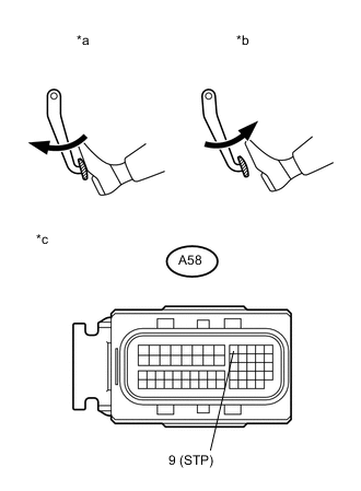
Text in Illustration *a Brake Pedal Depressed *b Brake Pedal Released *c Front view of wire harness connector
(to ECM)
Disconnect the ECM connector.
-
Measure the voltage according to the value(s) in the table below.
Standard Voltage Tester Connection Brake Pedal Operation Specified Condition A58-9 (STP) - Body ground Released Below 1.5 V Depressed 7.5 to 14 V -
Reconnect the ECM connector.
OK
REPLACE ECM Click here
NG
REPAIR OR REPLACE HARNESS OR CONNECTOR (STOP LIGHT SWITCH ASSEMBLY - ECM)
-