SFI SYSTEM Starter Signal Circuit
DESCRIPTION
-
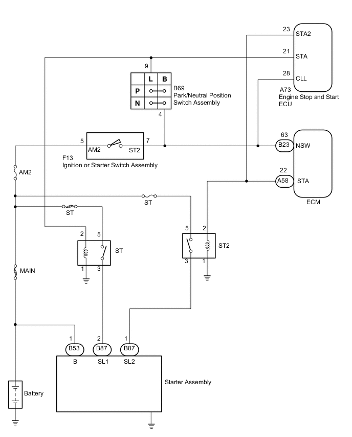
When cranking the engine, the starter motor drive signal (STA2 signal) transmitted by the engine stop and start ECU is received by the ECM as the starter operation signal (STA signal), and then the ECM controls the engine. When the ignition or starter switch assembly is turned to ON and the battery voltage is applied to the engine stop and start ECU through the park/neutral position switch assembly, the engine stop and start ECU transmits the starter operation signal (STA signal) to the ST relay (starter pinion drive relay). Afterwards, the engine stop and start ECU transmits the starter motor drive signal (STA2 signal) to the ST2 relay through the delay circuit.
w/o Entry and Start System
WIRING DIAGRAM
CAUTION / NOTICE / HINT
Note
Inspect the fuses for circuits related to this system before performing the following inspection procedure.
PROCEDURE
-
CHECK WHETHER ENGINE CAN BE CRANKED
-
Check if the engine can be cranked.
Result Result Proceed to Engine cannot be cranked A Engine can be cranked B
B 
READ VALUE USING GTS (STARTER SIGNAL) Click here
A 
-
-
READ VALUE USING GTS (STARTER SIGNAL)
-
Connect the GTS to DLC3.
-
Turn the ignition switch to ON.
-
Turn the GTS on.
-
Enter the following menus: Powertrain / Engine and ECT / Data List / All Data / Starter Signal.
-
Read the value displayed on the GTS when the ignition switch is turned to ON and START.
OK Switch Position Starter Signal ON Close (OFF) START Open (ON)
OK 
GO TO ENGINE STOP AND START SYSTEM Click here
NG
-
-
CHECK HARNESS AND CONNECTOR (ECM - ENGINE STOP AND START ECU - ST2 RELAY)
-
Disconnect the ECM connector.
-
Disconnect the engine stop and start ECU connector.
-
Remove the ST2 relay from the engine room relay block.
-
Measure the resistance according to the value(s) in the table below.
Standard Resistance Tester Connection Condition Specified Condition A58-22 (STA) - A73-23 (STA2) Always Below 1 Ω A58-22 (STA) - ST2 relay terminal 2 Always Below 1 Ω A58-22 (STA) - Body ground Always 10 kΩ or higher A73-23 (STA2) - Body ground Always 10 kΩ or higher ST2 relay terminal 2 - Body ground Always 10 kΩ or higher
NG
REPAIR OR REPLACE HARNESS OR CONNECTOR (ECM - ENGINE STOP AND START ECU - ST2 RELAY)
OK
-
-
CHECK HARNESS AND CONNECTOR (ECM - ENGINE STOP AND START ECU - PARK / NEUTRAL POSITION SWITCH - IGNITION OR STARTER SWITCH)
-
Disconnect the ECM connector.
-
Disconnect the engine stop and start ECU connector.
-
Disconnect the park/neutral position switch assembly connector.
-
Disconnect the ignition or starter switch assembly connector.
-
Measure the resistance according to the value(s) in the table below.
Standard Resistance Tester Connection Condition Specified Condition B23-63 (NSW) - A73-28 (CLL) Always Below 1 Ω B23-63 (NSW) - B69-4 (B) Always Below 1 Ω B23-63 (NSW) - F13-7 (ST2) Always Below 1 Ω B23-63 (NSW) - Body ground Always 10 kΩ or higher A73-28 (CLL) - Body ground Always 10 kΩ or higher B69-4 (B) - Body ground Always 10 kΩ or higher F13-7 (ST2) - Body ground Always 10 kΩ or higher
OK
GO TO PROCEED TO NEXT SUSPECTED AREA SHOWN IN PROBLEM SYMPTOMS TABLE Click here
NG
REPAIR OR REPLACE HARNESS AND CONNECTOR (ECM - ENGINE STOP AND START ECU - PARK / NEUTRAL POSITION SWITCH - IGNITION OR STARTER SWITCH)
-
-
READ VALUE USING GTS (STARTER SIGNAL)
-
Connect the GTS to DLC3.
-
Turn the ignition switch to ON.
-
Turn the GTS on.
-
Enter the following menus: Powertrain / Engine and ECT / Data List / All Data / Starter Signal.
-
Read the value displayed on the GTS when the ignition switch is turned to ON and START.
OK Switch Position Starter Signal ON Close (OFF) START Open (ON)
OK
GO TO PROCEED TO NEXT SUSPECTED AREA SHOWN IN PROBLEM SYMPTOMS TABLE Click here
NG
REPAIR OR REPLACE HARNESS AND CONNECTOR (ECM - ST2 RELAY)
-