SFI SYSTEM, Diagnostic DTC:P0335, P0337, P0338, P0339
| DTC Code | DTC Name |
|---|---|
| P0335 | Crankshaft Position Sensor "A" Circuit |
| P0337 | Crankshaft Position Sensor "A" Circuit Low Input |
| P0338 | Crankshaft Position Sensor "A" Circuit High Input |
| P0339 | Crankshaft Position Sensor "A" Circuit Intermittent |
DESCRIPTION
The crank position sensor system consists of a crankshaft angle sensor plate (crankshaft) and Magneto Resistive Element (MRE) type sensor. The crankshaft angle sensor plate has 34 teeth (2 teeth are missing for detecting top dead center), and is installed on the crankshaft. The crank position sensor generates 34 signals per crankshaft revolution. The ECM uses the NE signal to detect the crankshaft position and engine speed.
| DTC No. | DTC Detection Condition | Trouble Area |
|---|---|---|
| P0335*1 | When one of the following conditions is met (1 trip detection logic):
|
|
| P0337*1 | Output voltage of crank position sensor 0.3 V or less for 0.43 seconds (1 trip detection logic). |
|
| P0338*1 | Output voltage of crank position sensor 4.7 V or more for 0.43 seconds (1 trip detection logic). |
|
| P0339*1 | No crank position sensor signal to ECM while engine speed 1000 rpm or more for 0.05 seconds or more (1 trip detection logic). |
|
*1: When the engine is stopped and started automatically due to Stop and Start system control, the crank position sensor does not monitor during the automatic cranking.
-
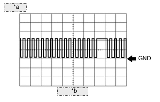
*a 2 V/DIV. *b 10 ms./DIV. Reference: Inspection using an oscilloscope.
Tech Tips
The correct waveform is as shown.
ECM Terminal Name Between NE+ and NE- Tester Range 2 V/DIV., 10 ms./DIV. Condition Idling with warm engine
MONITOR DESCRIPTION
If there is no signal from the crank position sensor despite the crankshaft revolving, the ECM interprets this as a malfunction of the sensor.
When the sensor output voltage remains at below 0.3 V, or higher than 4.7 V for more than 0.43 seconds, the ECM stores a DTC.
MONITOR STRATEGY
| Required Sensors/Components (Main) | Crank position sensor |
| Required Sensors/Components (Related) | Camshaft position sensor |
| Frequency of Operation | Continuous |
COMPONENT OPERATING RANGE
| Crank position sensor |
|
CONFIRMATION DRIVING PATTERN
-
Connect the GTS to the DLC3.
-
Turn the ignition switch to ON.
-
Turn the GTS on.
-
Clear DTCs (even if no DTCs are stored, perform the clear DTC operation)
-
Turn the ignition switch off and wait for at least 30 seconds.
-
Start the engine.
-
Idle the engine for 20 seconds or more.
-
Turn the GTS on.
-
Enter the following menus: Powertrain / Engine and ECT / DTC.
-
Read pending DTCs.
Tech Tips
-
If a pending DTC is output, the system is malfunctioning.
-
If a pending DTC is not output, perform the following procedure.
-
-
Enter the following menus: Powertrain / Engine and ECT / Utility / All Readiness.
-
Input the DTC: P0335, P0337, P0338 or P0339.
-
Check the DTC judgment result.
Tester Display Description NORMAL
-
DTC judgment completed
-
System normal
ABNORMAL
-
DTC judgment completed
-
System abnormal
INCOMPLETE
-
DTC judgment not completed
-
Perform driving pattern after confirming DTC enabling conditions
N/A
-
Unable to perform DTC judgment
-
Number of DTCs which do not fulfill DTC preconditions has reached ECU memory limit
Tech Tips
-
If the judgment result shows NORMAL, the system is normal.
-
If the judgment result shows ABNORMAL, the system has a malfunction.
-
If the judgment result shows INCOMPLETE or N/A, perform the Confirmation Driving Pattern and the DTC judgment result again.
-
WIRING DIAGRAM
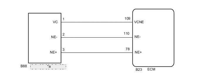
| *a | Crank Position Sensor |
CAUTION / NOTICE / HINT
Tech Tips
-
If no problem is found through this diagnostic troubleshooting procedure, troubleshoot the engine mechanical system.
-
Check the engine speed. The engine speed can be checked by using the GTS. Follow the procedure below:
-
Connect the GTS to the DLC3.
-
Start the engine.
-
Turn the GTS on.
-
Enter the following menus: Powertrain / Engine and ECT / Data List / Engine Speed.
-
The engine speed may be indicated as zero despite the engine revolving normally. This is caused by a lack of NE signals from the crank position sensor. Alternatively, the engine speed may be indicated as lower than the actual engine speed if the crank position sensor output voltage is insufficient.
-
Read freeze frame data using the GTS. Freeze frame data records the engine conditions when malfunctions are detected. When troubleshooting, freeze frame data can help determine if the vehicle was moving or stationary, if the engine was warmed up or not, if the air-fuel ratio was lean or rich, and other data from the time the malfunction occurred.
PROCEDURE
-
READ VALUE USING GTS (ENGINE SPEED)
-
Connect the GTS to the DLC3.
-
Turn the ignition switch to ON.
-
Turn the GTS on.
-
Enter the following menus: Powertrain / Engine and ECT / Data List / Engine Speed.
-
Start the engine.
-
Read the values displayed on the GTS while the engine is running.
OK Correct values are displayed. Tech Tips
-
To check the engine speed change, display the graph on the GTS.
-
If the engine does not start, check the engine speed while cranking.
-
If the engine speed indicated on the GTS remains zero (0), there may be an open or short in the crank position sensor circuit.
-
OK 
CHECK FOR INTERMITTENT PROBLEMS Click here
NG 
-
-
CHECK TERMINAL VOLTAGE (POWER SOURCE OF CRANK POSITION SENSOR)
-
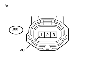
Text in Illustration *a Front view of wire harness connector
(to Crank Position Sensor)
Disconnect the crank position sensor connector.
-
Turn the ignition switch to ON.
-
Measure the voltage according to the value(s) in the table below.
Standard Voltage Tester Connection Switch Condition Specified Condition B88-1 (VC) - Body ground Ignition switch ON 4.5 to 5.5 V
NG 
CHECK HARNESS AND CONNECTOR (CRANK POSITION SENSOR - ECM) Click here
OK
-
-
CHECK HARNESS AND CONNECTOR (CRANK POSITION SENSOR - ECM)
-
Disconnect the crank position sensor connector.
-
Disconnect the ECM connector.
-
Measure the resistance according to the value(s) in the table below.
Standard Resistance Tester Connection Condition Specified Condition B88-3 (NE+) - B23-78 (NE+) Always Below 1 Ω B88-2 (NE-) - B23-110 (NE-) Always Below 1 Ω B88-3 (NE+) or B23-78 (NE+) - Body ground Always 10 kΩ or higher B88-2 (NE-) or B23-110 (NE-) - Body ground Always 10 kΩ or higher
NG
REPAIR OR REPLACE HARNESS OR CONNECTOR
OK
-
-
CHECK SENSOR INSTALLATION (CRANK POSITION SENSOR)
-
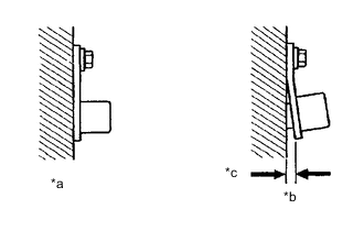
Text in Illustration *a OK *b NG *c Clearance Check the crank position sensor installation.
OK Sensor is installed correctly.
NG
SECURELY REINSTALL CRANKSHAFT POSITION SENSOR Click here
OK
-
-
INSPECT CRANKSHAFT (CRANKSHAFT ANGLE SENSOR PLATE)
-
Check the teeth of the crankshaft angle sensor plate.
OK Teeth do not have any cracks or deformation.
NG
REPLACE CRANKSHAFT (CRANKSHAFT ANGLE SENSOR PLATE) Click here
OK
-
-
REPLACE CRANKSHAFT POSITION SENSOR
-
Replace the crank position sensor Click here.
NEXT
-
-
CHECK WHETHER DTC OUTPUT RECURS
-
Connect the GTS to the DLC3.
-
Turn the ignition switch to ON.
-
Turn the GTS on.
-
Clear the DTCs Click here.
-
Turn the ignition switch off and wait for at least 30 seconds.
-
Start the engine.
-
Drive the vehicle in accordance with the driving pattern described in Confirmation Driving Pattern.
-
Enter the following menus: Powertrain / Engine and ECT / DTC.
-
Read DTCs.
Result Result Proceed to DTC is not output A DTC P0335, P0337, P0338 and/or P0339 is output B
A
END
B
REPLACE ECM Click here
-
-
CHECK HARNESS AND CONNECTOR (CRANK POSITION SENSOR - ECM)
-
Disconnect the crank position sensor connector.
-
Disconnect the ECM connector.
-
Measure the resistance according to the value(s) in the table below.
Standard Resistance Tester Connection Condition Specified Condition B88-1 (VC) - B23-109 (VCNE) Always Below 1 Ω B88-1 (VC) or B23-109 (VCNE) - Body ground Always 10 kΩ or higher
OK
REPLACE ECM Click here
NG
REPAIR OR REPLACE HARNESS OR CONNECTOR
-