SFI SYSTEM, Diagnostic DTC:P2237, P2238, P2239, P2252, P2253
| DTC Code | DTC Name |
|---|---|
| P2237 | Oxygen (A/F) Sensor Pumping Current Circuit / Open (Bank 1 Sensor 1) |
| P2238 | Oxygen (A/F) Sensor Pumping Current Circuit Low (Bank 1 Sensor 1) |
| P2239 | Oxygen (A/F) Sensor Pumping Current Circuit High (Bank 1 Sensor 1) |
| P2252 | Oxygen (A/F) Sensor Reference Ground Circuit Low (Bank 1 Sensor 1) |
| P2253 | Oxygen (A/F) Sensor Reference Ground Circuit High (Bank 1 Sensor 1) |
DESCRIPTION
Tech Tips
-
Although the DTC titles say oxygen sensor, these DTCs relate to the air fuel ratio sensor.
-
Sensor 1 refers to the sensor mounted in front of the three-way catalytic converter and located near the engine assembly.
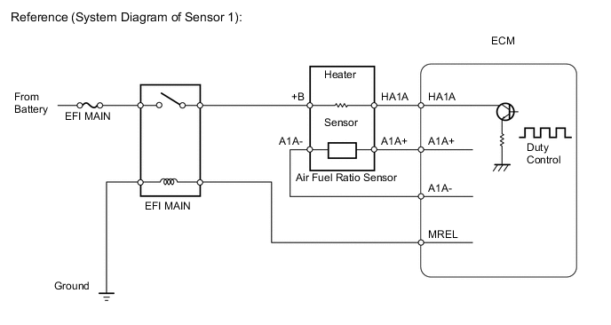
The air fuel ratio sensor, which is located between the exhaust manifold and catalyst, consists of alloyed metal elements and a heater.
Depending on the engine operating conditions, the heater heats the sensor elements to activate them. Battery voltage is applied to the heater, and the sensor ground is controlled by the ECM using a duty ratio.
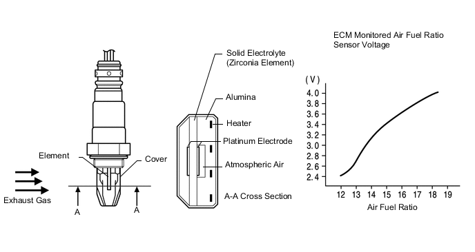
The sensor elements convert the oxygen concentration in the exhaust gas into voltage values to output. Based on the voltage, the ECM determines the air fuel ratio and regulates the fuel injection volume depending on the air fuel ratio and engine operating conditions. The voltage changes between 0.6 V and 4.5 V while the engine is running. If the air fuel ratio is lean, which means that the oxygen concentration in the exhaust gas is high, the voltage is high. If the air fuel ratio is rich, which means that the oxygen concentration in the exhaust gas is low, the voltage is low.
| DTC No. | DTC Detection Condition | Trouble Area |
|---|---|---|
| P2237 | Open in the circuit between terminals A1A+ and A1A- of the air fuel ratio sensor while engine is running (2 trip detection logic) |
|
| P2238 | Any of the following conditions are met (2 trip detection logic)
|
|
| P2239 | A1A+ voltage is more than 4.5 V (2 trip detection logic) |
|
| P2252 | A1A- voltage is 0.5 V or less (2 trip detection logic) |
|
| P2253 | A1A- voltage is more than 4.5 V (2 trip detection logic) |
|
MONITOR DESCRIPTION
These DTCs are output when there is an open or short in the air fuel ratio sensor circuit, or if the air fuel ratio sensor output drops.
To detect these problems, the voltage of the air fuel ratio sensor is monitored when turning the ignition switch to ON, and the admittance (admittance is an electrical term that indicates the ease of flow of current) is checked while driving. If the voltage of the air fuel ratio sensor is between 0.6 V and 4.5 V, it is considered normal. If the voltage is outside of the specified range, or the admittance is below the standard value, the ECM will determine that there is a malfunction in the air fuel ratio sensor. If the same malfunction is detected in the next driving cycle, the MIL is illuminated and a DTC is stored.
The air fuel ratio sensor varies its output voltage in proportion to the air-fuel ratio. If the air fuel ratio sensor impedance (alternating current resistance) or output voltage deviates greatly from the standard range, the ECM determines that there is an open or short in the air fuel ratio sensor circuit.
CONFIRMATION DRIVING PATTERN
-
Turn the ignition switch to ON and wait for 5 seconds or more.
WIRING DIAGRAM
Refer to DTC P0031 Click here.
CAUTION / NOTICE / HINT
Tech Tips
-
Refer to "Data List / Active Test" [AFS Voltage B1S1] Click here.
-
Read freeze frame data using the intelligent tester. Freeze frame data records the engine conditions when malfunctions are detected. When troubleshooting, freeze frame data can help determine if the vehicle was moving or stationary, if the engine was warmed up or not, if the air-fuel ratio was lean or rich, and other data from the time the malfunction occurred.
-
Sensor 1 refers to the sensor closest to the engine assembly.
-
Sensor 2 refers to the sensor farthest away from the engine assembly.
PROCEDURE
-
PERFORM ACTIVE TEST USING INTELLIGENT TESTER (CONTROL THE EGR STEP POSITION)
-
Connect the intelligent tester to the DLC3.
-
Start the engine and turn the tester on.
-
Enter the following menus: Powertrain / Engine and ECT / Active Test / Control the EGR Step Position.
OK EGR Step Position Specified Condition 0 step Normal engine speed 0 → 100 step Engine idles roughly or stalls
NG 
INSPECT EGR PIPE CONNECTOR Click here
OK 
-
-
CHECK HARNESS AND CONNECTOR (AIR FUEL RATIO SENSOR - ECM)
-
Disconnect the air fuel ratio sensor connector.
-
Disconnect the ECM connector.
-
Measure the resistance according to the value(s) in the table below.
Standard Resistance (Check for Open) for RHD Tester Connection Condition Specified Condition B39-1 (HA1A) - B23-23 (HA1A) Always Below 1 Ω B39-3 (A1A+) - B23-133 (A1A+) Always Below 1 Ω B39-4 (A1A-) - B23-134 (A1A-) Always Below 1 Ω for LHD Tester Connection Condition Specified Condition B39-1 (HA1A) - B22-23 (HA1A) Always Below 1 Ω B39-3 (A1A+) - B22-133 (A1A+) Always Below 1 Ω B39-4 (A1A-) - B22-134 (A1A-) Always Below 1 Ω Standard Resistance (Check for Short) for RHD Tester Connection Condition Specified Condition B39-1 (HA1A) or B23-23 (HA1A) - Body ground Always 10 kΩ or higher B39-3 (A1A+) or B23-133 (A1A+) - Body ground Always 10 kΩ or higher B39-4 (A1A-) or B23-134 (A1A-) - Body ground Always 10 kΩ or higher for LHD Tester Connection Condition Specified Condition B39-1 (HA1A) or B22-23 (HA1A) - Body ground Always 10 kΩ or higher B39-3 (A1A+) or B22-133 (A1A+) - Body ground Always 10 kΩ or higher B39-4 (A1A-) or B22-134 (A1A-) - Body ground Always 10 kΩ or higher -
Reconnect the air fuel ratio sensor connector.
-
Reconnect the ECM connector.
NG 
REPAIR OR REPLACE HARNESS OR CONNECTOR
OK
-
-
REPLACE AIR FUEL RATIO SENSOR
-
Replace the air fuel ratio sensor Click here.
Tech Tips
Perform "Inspection After Repairs" after replacing the air fuel ratio sensor Click here.
NEXT
-
-
PERFORM CONFIRMATION DRIVING PATTERN
-
Connect the intelligent tester to the DLC3.
-
Turn the ignition switch to ON.
-
Turn the tester on.
-
Clear the DTCs Click here.
-
Switch the ECM from normal mode to check mode Click here.
-
Drive the vehicle referring to the Confirmation Driving Pattern on DTC P2195 Click here.
NEXT
-
-
CHECK WHETHER DTC OUTPUT RECURS (DTC P2237, P2238, P2239, P2252 OR P2253)
-
Connect the intelligent tester to the DLC3.
-
Turn the ignition switch to ON.
-
Turn the tester on.
-
Enter the following menus: Powertrain / Engine and ECT / DTC.
-
Read the DTCs.
Result Result Proceed to DTC is not output A DTC P2237, P2238, P2239, P2252 or P2253 is output B
A
END
B
REPLACE ECM Click here
-
-
INSPECT EGR PIPE CONNECTOR
-
Check the EGR pipe connector for leaks or blockage.
OK No leaks or blockage
NG
REPAIR OR REPLACE EGR PIPE CONNECTOR Click here
OK
-
-
INSPECT EGR VALVE ASSEMBLY (VISUALLY CHECK EGR VALVE)
-
Remove the EGR valve assembly Click here.
-
Check for contamination between the EGR valve and housing.
OK EGR valve is not contaminated with foreign objects. -
Reinstall the EGR valve assembly Click here.
OK
REPLACE ECM Click here
NG
REPLACE EGR VALVE ASSEMBLY Click here
-