SFI SYSTEM, Diagnostic DTC:P0443
| DTC Code | DTC Name |
|---|---|
| P0443 | Evaporative Emission Control System Purge Control Valve Circuit |
DESCRIPTION
To reduce hydrocarbon emissions, fuel vapor from the fuel tank is routed through a charcoal canister to the intake manifold for combustion in the cylinders.
The ECM changes the duty signals to the purge VSV (vacuum switching valve assembly) so that the intake amount of hydrocarbon emissions is appropriate for the driving conditions (engine load, engine speed, vehicle speed, etc.) after the engine is warmed up.
| DTC No. | DTC Detection Condition | Trouble Area |
|---|---|---|
| P0443 | All of the following conditions (a) and (b) are met (1 trip detection logic) (a) The target control value and actual control value do not match for 10 seconds or more. (b) The target control value and actual control value are detected 80 time or more. |
|
CONFIRMATION DRIVING PATTERN
-
Connect the intelligent tester to the DLC3.
-
Turn the ignition switch to ON and turn the intelligent tester on.
-
Clear the DTCs (even if no DTCs are stored, perform the clear DTC operation).
-
Turn the ignition switch off and wait for at least 30 seconds.
-
Turn the ignition switch to ON and turn the intelligent tester on.
-
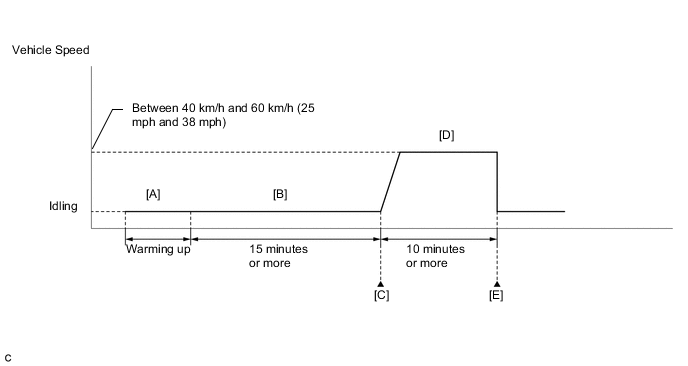
Start the engine and warm it up until the engine coolant temperature is 75°C (167°F) or higher [A].
Tech Tips
The A/C switch and all accessory switches should be off.
-
Idle the engine for 15 minutes or more [B].
Tech Tips
Check the EVAP (Purge) VSV item in the Data List. When the value of this item is between 5 and 95%, the judgment will be performed.
-
Enter the following menus: Powertrain / Engine and ECT / DTC [C].
-
Read the pending DTCs.
Tech Tips
-
If a pending DTC is output, the system is malfunctioning.
-
If a pending DTC is not output, perform the following procedure.
-
-
Enter the following menus: Powertrain / Engine and ECT / Utility / All Readiness.
-
Input the DTC: P0443.
-
Check the DTC judgment result.
Tester Display Description NORMAL
-
DTC judgment completed
-
System normal
ABNORMAL
-
DTC judgment completed
-
System abnormal
INCOMPLETE
-
DTC judgment not completed
-
Perform driving pattern after confirming DTC enabling conditions
UNKNOWN
-
Unable to perform DTC judgment
-
Number of DTCs which do not fulfill DTC preconditions has reached ECU memory limit
Tech Tips
-
If the judgment result shows NORMAL, the system is normal.
-
If the judgment result shows ABNORMAL, the system has a malfunction.
-
If the judgment result shows INCOMPLETE or UNKNOWN, perform steps [D] and [E].
-
-
Drive the vehicle at a constant speed between 40 and 60 km/h (25 and 38 mph) for 10 minutes [D].
CAUTION:
When performing the confirmation driving pattern, obey all speed limits and traffic laws.
-
Check the DTC judgment result [E].
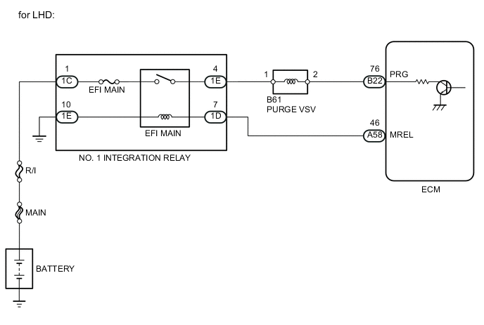
WIRING DIAGRAM

CAUTION / NOTICE / HINT
Note
Inspect the fuse for circuits related to this system before performing the following inspection procedure.
Tech Tips
Read freeze frame data using the intelligent tester. Freeze frame data records the engine conditions when malfunctions are detected. When troubleshooting, freeze frame data can help determine if the vehicle was moving or stationary, if the engine was warmed up or not, if the air-fuel ratio was lean or rich, and other data from the time the malfunction occurred.
PROCEDURE
-
PERFORM ACTIVE TEST USING INTELLIGENT TESTER (ACTIVATE THE PURGE VSV CONTROL)
-
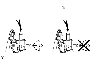
Text in Illustration *a VSV is on *b VSV is off Connect the intelligent tester to the DLC3.
-
Disconnect the charcoal canister side vacuum hose from the purge VSV from the charcoal canister.
-
Start the engine.
-
Turn the tester on.
-
Enter the following menus: Powertrain / Engine and ECT / Active Test / Activate the VSV for Evap Control.
-
When the purge VSV is operated using the intelligent tester, check whether the port of the purge VSV applies suction to your finger.
OK Tester Operation Specified Condition VSV is ON Purge VSV port applies suction to finger VSV is OFF Purge VSV port applies no suction to finger -
Reconnect the vacuum hose to the purge VSV.
OK 
CHECK FOR INTERMITTENT PROBLEMS Click here
NG 
-
-
INSPECT PURGE VSV
-
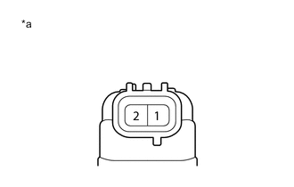
Text in Illustration *a Component without harness connected
(Purge VSV)
Disconnect the purge VSV connector.
-
Measure the resistance according to the value(s) in the table below.
Standard Resistance Tester Connection Condition Specified Condition 1 - 2 20°C (68°F) 23 to 26 Ω -
Reconnect the purge VSV connector.
NG
REPLACE PURGE VSV (VACUUM SWITCHING VALVE ASSEMBLY) Click here
OK
-
-
INSPECT PURGE VSV (POWER SOURCE VOLTAGE)
-
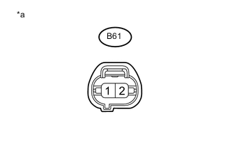
Text in Illustration *a Front view of wire harness connector
(to Purge VSV)
Disconnect the purge VSV connector.
-
Turn the ignition switch to ON.
-
Measure the voltage according to the value(s) in the table below.
Standard Voltage Tester Connection Switch Condition Specified Condition B61-1 - Body ground Ignition switch ON 11 to 14 V -
Reconnect the purge VSV connector.
NG
REPAIR OR REPLACE HARNESS OR CONNECTOR (PURGE VSV - NO. 1 INTEGRATION RELAY (EFI MAIN RELAY))
OK
-
-
CHECK HARNESS AND CONNECTOR (PURGE VSV - ECM)
-
Disconnect the purge VSV connector.
-
Disconnect the ECM connector.
-
Measure the resistance according to the value(s) in the table below.
Standard Resistance (Check for Open) for RHD Tester Connection Condition Specified Condition B61-2 - B23-76 (PRG) Always Below 1 Ω for LHD Tester Connection Condition Specified Condition B61-2 - B22-76 (PRG) Always Below 1 Ω Standard Resistance (Check for Short) for RHD Tester Connection Condition Specified Condition B61-2 or B23-76 (PRG) - Body ground Always 10 kΩ or higher for LHD Tester Connection Condition Specified Condition B61-2 or B22-76 (PRG) - Body ground Always 10 kΩ or higher -
Reconnect the purge VSV connector.
-
Reconnect the ECM connector.
OK
REPLACE ECM Click here
NG
REPAIR OR REPLACE HARNESS OR CONNECTOR (PURGE VSV - ECM)
-