SFI SYSTEM, Diagnostic DTC:P0403
| DTC Code | DTC Name |
|---|---|
| P0403 | Exhaust Gas Recirculation Control Circuit |
DESCRIPTION
The ECM lowers combustion chamber temperatures and reduces Nitrogen Oxide (NOx) emissions by recirculating an appropriate amount of exhaust gas to the combustion chambers according to the engine operating conditions. When all EGR activation conditions are met (based on sensor signals such as engine speed, coolant temperature, load signal, vehicle speed signal), the ECM turns on the stepper motor inside the EGR valve and linearly controls the opening angle of the EGR valve. When the ECM determines that EGR operation will not influence engine operating conditions, the ECM forcibly opens and closes the EGR valve to monitor changes in manifold pressure. If the manifold pressure change is less than that during normal EGR valve operation, the ECM will detect a shortage of EGR gas flow and set a DTC. Also, an EGR DTC is set if a malfunction (open or short circuit) occurs in the EGR valve operation circuit.
| DTC No. | DTC Detection Condition | Trouble Area |
|---|---|---|
| P0403 | Both of the following conditions are met for 1 second or more (1 trip detection logic):
|
|
MONITOR DESCRIPTION
This DTC is designed to detect an open or short is the EGR valve circuit.
If the EGR terminal voltage is low when the EGR terminal output is off, the ECM determines that the EGR valve circuit is malfunctioning.
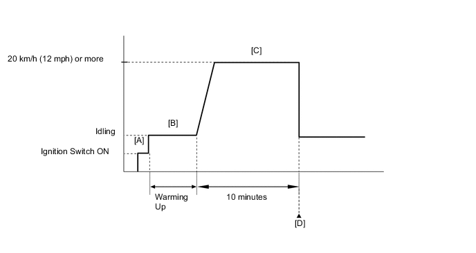
CONFIRMATION DRIVING PATTERN
-
Connect the intelligent tester to the DLC3.
-
Turn the ignition switch to ON and turn the tester on [A].
-
Clear the DTCs (even if no DTCs are stored, perform the clear DTC procedure) Click here.
-
Start the engine and warm it up [B].
-
Drive the vehicle at 20 km/h (12 mph) or more for 10 minutes [C].
CAUTION:
When performing the confirmation driving pattern, obey all speed limits and traffic laws.
-
Enter the following menus: Powertrain / Engine and ECT / DTC [D].
-
Read the pending DTCs.
Tech Tips
-
If a pending DTC is output, the system is malfunctioning.
-
If a pending DTC is not output, perform the following procedure.
-
-
Enter the following menus: Powertrain / Engine and ECT / Utility / All Readiness.
-
Input the DTC: P0403.
-
Check the DTC judgment result.
Tester Display Description NORMAL
-
DTC judgment completed
-
System normal
ABNORMAL
-
DTC judgment completed
-
System abnormal
INCOMPLETE
-
DTC judgment not completed
-
Perform driving pattern after confirming DTC enabling conditions
UNKNOWN
-
Unable to perform DTC judgment
-
Number of DTCs which do not fulfill DTC preconditions has reached ECU memory limit
Tech Tips
-
If the judgment result shows NORMAL, the system is normal.
-
If the judgment result shows ABNORMAL, the system has a malfunction.
-
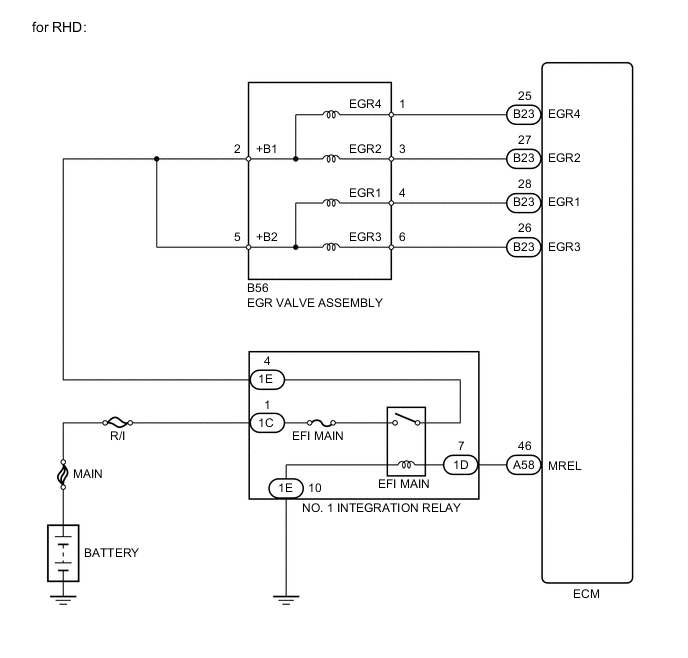
WIRING DIAGRAM

CAUTION / NOTICE / HINT
Note
Inspect the fuses for circuits related to this system before performing the following inspection procedure.
Tech Tips
Read freeze frame data using the intelligent tester. Freeze frame data records the engine conditions when malfunctions are detected. When troubleshooting, freeze frame data can help determine if the vehicle was moving or stationary, if the engine was warmed up or not, if the air-fuel ratio was lean or rich, and other data from the time the malfunction occurred.
PROCEDURE
-
PERFORM ACTIVE TEST USING ACTIVE TEST USING INTELLIGENT TESTER (CONTROL THE EGR STEP POSITION)
-
Connect the intelligent tester to the DLC3.
-
Turn the ignition switch to ON.
-
Turn the tester on.
-
Start the engine and warm it up until the engine coolant temperature reaches 75°C (167°F) or more.
Tech Tips
The A/C switch and all accessory switches should be off.
-
Enter the following menus: Powertrain / Engine and ECT / Active Test / Control the EGR Step Position.
-
Confirm that the Throttle Idle Position is ON and check the engine idling condition and MAP values in the Data List while performing the Active Test.
OK MAP and idling condition change in response to EGR step position. Standard - EGR Step Position (Active Test) 0 Steps 0 to 30 Steps Idling condition Steady idling Idling changes from steady to rough idling MAP
(Data List)
MAP value is 28 to 48 kPa
(210 to 360 mmHg)
(EGR valve is fully closed)
MAP value is at least +10 kPa (75 mmHg) higher than when EGR valve is fully closed Tech Tips
-
Do not leave the EGR valve open for 10 seconds or more during the Active Test.
-
Be sure to return the EGR valve to step 0 when the Active Test is completed.
-
During Active Test, if the idling condition does not change in response to EGR step position, then there is probably a malfunction in the EGR valve.
Result Result Proceed to Outside of standard range A Within standard range B -
B 
CHECK FOR INTERMITTENT PROBLEMS Click here
A 
-
-
INSPECT EGR VALVE ASSEMBLY
-
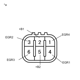
Text in Illustration *a Component without harness connected
(EGR Valve Assembly)
Disconnect the EGR valve assembly connector.
-
Measure the resistance according to the value(s) in the table below.
Standard Resistance Tester Connection Condition Specified Condition 5 (+B2) - 4 (EGR1) 20°C (68°F) 18 to 22 Ω 5 (+B2) - 6 (EGR3) 20°C (68°F) 18 to 22 Ω 2 (+B1) - 3 (EGR2) 20°C (68°F) 18 to 22 Ω 2 (+B1) - 1 (EGR4) 20°C (68°F) 18 to 22 Ω -
Reconnect the EGR valve assembly connector.
NG
REPLACE EGR VALVE ASSEMBLY Click here
OK
-
-
INSPECT EGR VALVE ASSEMBLY (VOLTAGE)
-
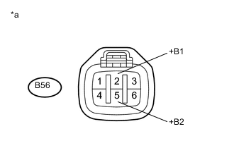
Text in Illustration *a Front view of wire harness connector
(to EGR Valve Assembly)
Disconnect the EGR valve assembly connector.
-
Turn the ignition switch to ON.
-
Measure the voltage according to the value(s) in the table below.
Standard Voltage Tester Connection Switch Condition Specified Condition B56-2 (+B1) - Body ground Ignition switch ON 11 to 14 V B56-5 (+B2) - Body ground Ignition switch ON 11 to 14 V -
Reconnect the EGR valve assembly connector.
NG 
CHECK HARNESS AND CONNECTOR (EGR VALVE ASSEMBLY - NO. 1 INTEGRATION RELAY) Click here
OK
-
-
CHECK HARNESS AND CONNECTOR (EGR VALVE ASSEMBLY - ECM)
-
Disconnect the EGR valve assembly connector.
-
Disconnect the ECM connector.
-
Measure the resistance according to the value(s) in the table below.
Standard Resistance (Check for Open) for RHD Tester Connection Condition Specified Condition B56-4 (EGR1) - B23-28 (EGR1) Always Below 1 Ω B56-3 (EGR2) - B23-27 (EGR2) Always Below 1 Ω B56-6 (EGR3) - B23-26 (EGR3) Always Below 1 Ω B56-1 (EGR4) - B23-25 (EGR4) Always Below 1 Ω for LHD Tester Connection Condition Specified Condition B56-4 (EGR1) - B22-28 (EGR1) Always Below 1 Ω B56-3 (EGR2) - B22-27 (EGR2) Always Below 1 Ω B56-6 (EGR3) - B22-26 (EGR3) Always Below 1 Ω B56-1 (EGR4) - B22-25 (EGR4) Always Below 1 Ω Standard Resistance (Check for Short) for RHD Tester Connection Condition Specified Condition B56-4 (EGR1) or B23-28 (EGR1) - Body ground Always 10 kΩ or higher B56-3 (EGR2) or B23-27 (EGR2) - Body ground Always 10 kΩ or higher B56-6 (EGR3) or B23-26 (EGR3) - Body ground Always 10 kΩ or higher B56-1 (EGR4) or B23-25 (EGR4) - Body ground Always 10 kΩ or higher for LHD Tester Connection Condition Specified Condition B56-4 (EGR1) or B22-28 (EGR1) - Body ground Always 10 kΩ or higher B56-3 (EGR2) or B22-27 (EGR2) - Body ground Always 10 kΩ or higher B56-6 (EGR3) or B22-26 (EGR3) - Body ground Always 10 kΩ or higher B56-1 (EGR4) or B22-25 (EGR4) - Body ground Always 10 kΩ or higher -
Reconnect the EGR valve assembly connector.
-
Reconnect the ECM connector.
OK
REPLACE ECM Click here
NG
REPAIR OR REPLACE HARNESS OR CONNECTOR
-
-
CHECK HARNESS AND CONNECTOR (EGR VALVE ASSEMBLY - NO. 1 INTEGRATION RELAY)
-
Disconnect the EGR valve assembly connector.
-
Remove the No. 1 integration relay from the engine room main relay block.
-
Measure the resistance according to the value(s) in the table below.
Standard Resistance (Check for Open) Tester Connection Condition Specified Condition B56-2 (+B1) - 1E-4 Always Below 1 Ω B56-5 (+B2) - 1E-4 Always Below 1 Ω Standard Resistance (Check for Short) Tester Connection Condition Specified Condition B56-2 (+B1) or 1E-4 - Body ground Always 10 kΩ or higher B56-5 (+B2) or 1E-4 - Body ground Always 10 kΩ or higher -
Reconnect the EGR valve assembly connector.
-
Reinstall the No. 1 integration relay.
OK
CHECK ECM POWER SOURCE CIRCUIT Click here
NG
REPAIR OR REPLACE HARNESS OR CONNECTOR
-