ECD SYSTEM, Diagnostic DTC:P06DA, P06DB, P06DC
| DTC Code | DTC Name |
|---|---|
| P06DA | Engine Oil Pressure Control Circuit Open |
| P06DB | Engine Oil Pressure Control Circuit Low |
| P06DC | Engine Oil Pressure Control Circuit High |
DESCRIPTION
Refer to DTC P0522 Click here
| DTC Detection Drive Pattern | DTC Detection Condition | Trouble Area |
|---|---|---|
| Ignition switch ON | Open or short in oil pressure switching valve assembly control circuit for 2 seconds or more. (1 trip detection logic) |
|
| DTC Detection Drive Pattern | DTC Detection Condition | Trouble Area |
|---|---|---|
| Ignition switch ON | Ground short or open in oil pressure switching valve assembly control circuit for 2 seconds or more. (1 trip detection trip) |
|
| DTC Detection Drive Pattern | DTC Detection Condition | Trouble Area |
|---|---|---|
| Ignition switch ON | Battery short in oil pressure switching valve assembly control circuit for 2 seconds or more. (1 trip detection trip) |
|
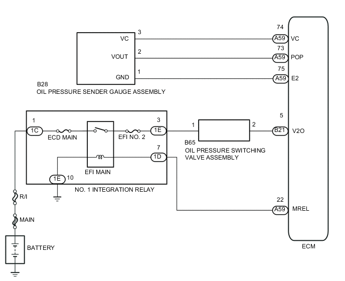
WIRING DIAGRAM
CAUTION / NOTICE / HINT
Note
-
When replacing the ECM, the ECM needs Registration and Initialization Click here.
-
Inspect the fuses for circuits related to this system before performing the following inspection procedure.
Tech Tips
-
Read freeze frame data using the intelligent tester. Freeze frame data records the engine condition when malfunctions are detected. When troubleshooting, freeze frame data can help determine if the vehicle was moving or stationary, if the engine was warmed up or not, and other data from the time the malfunction occurred.
-
An output DTC does not necessarily indicate that there is a malfunction. DTCs may have been stored due to an insufficient engine oil amount even though the oil level warning light is currently not illuminated, such as when engine oil is added by the customer.
PROCEDURE
-
INSPECT OIL PRESSURE SWITCHING VALVE ASSEMBLY
-
Inspect the oil pressure switching valve assembly Click here.
NG 
REPLACE OIL PRESSURE SWITCHING VALVE ASSEMBLY Click here
OK 
-
-
CHECK HARNESS AND CONNECTOR (PRESSURE CONTROL VALVE - ECM)
-
Disconnect the oil pressure switching valve assembly connector.
-
Disconnect the ECM connector.
-
Measure the resistance according to the value(s) in the table below.
Standard Resistance (Check for Open) Tester Connection Condition Specified Condition B65-2 - B21-5 (V2O) Always Below 1 Ω Standard Resistance (Check for Short) Tester Connection Condition Specified Condition B65-2 or B21-5 (V2O) - Body ground Always 10 kΩ or higher -
Reconnect the oil pressure switching valve assembly connector.
-
Reconnect the ECM connector.
NG
REPAIR OR REPLACE HARNESS OR CONNECTOR Click here
OK
-
-
CHECK HARNESS AND CONNECTOR (POWER SOURCE)
-
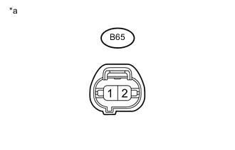
Text in Illustration *a Front view of wire harness connector
(to Oil Pressure Switching Valve Assembly)
Disconnect the oil pressure switching valve assembly connector.
-
Measure the voltage according to the value(s) in the table below.
Standard Voltage Tester Connection Switch Condition Specified Condition B65-1 (OSV+) - Body ground Ignition switch ON 11 to 14 V -
Reconnect the oil pressure switching valve assembly connector.
NG
CHECK HARNESS AND CONNECTOR (OIL PRESSURE SWITCHING VALVE - NO. 1 INTEGRATION RELAY) Click here
OK
-
-
CHECK WHETHER DTC OUTPUT RECURS
-
Connect the intelligent tester to the DLC3.
-
Clear the DTCs Click here.
-
Turn the ignition switch off and wait for 30 seconds or more.
-
Turn the ignition switch to ON and wait for 3 second or more.
-
Enter the following menus: Powertrain / Engine and ECT / DTC.
-
Read the DTCs.
Result Result Proceed to DTC P06DA, P06DB or P06DC A No DTC output B
B 
CHECK FOR INTERMITTENT PROBLEMS Click here
A
-
-
REPLACE ECM
-
Replace the ECM Click here.
NEXT
CONFIRM WHETHER MALFUNCTION HAS BEEN SUCCESSFULLY REPAIRED Click here
-
-
CHECK HARNESS AND CONNECTOR (OIL PRESSURE SWITCHING VALVE - NO. 1 INTEGRATION RELAY)
-
Disconnect the oil pressure switching valve assembly connector.
-
Remove the No. 1 integration relay from engine room main relay block.
-
Measure the resistance according to the value(s) in the table below.
Standard Resistance (Check for Open) Tester Connection Condition Specified Condition B65-1 - 1E-3 Always Below 1 Ω Standard Resistance (Check for Short) Tester Connection Condition Specified Condition B65-1 or 1E-3 - Body ground Always 10 kΩ or higher -
Reconnect the oil pressure switching valve assembly connector.
-
Reinstall the No. 1 integration relay.
NG
REPAIR OR REPLACE HARNESS OR CONNECTOR Click here
OK
-
-
CHECK ECM POWER SOURCE CIRCUIT
-
Check ECM power source circuit Click here.
NEXT
CONFIRM WHETHER MALFUNCTION HAS BEEN SUCCESSFULLY REPAIRED Click here
-
-
REPAIR OR REPLACE HARNESS OR CONNECTOR
NEXT
CONFIRM WHETHER MALFUNCTION HAS BEEN SUCCESSFULLY REPAIRED Click here
-
REPLACE OIL PRESSURE SWITCHING VALVE ASSEMBLY
-
Replace the oil pressure switching valve assembly Click here.
NEXT
-
-
CONFIRM WHETHER MALFUNCTION HAS BEEN SUCCESSFULLY REPAIRED
-
Connect the intelligent tester to the DLC3.
-
Clear the DTCs Click here.
-
Turn the ignition switch off and wait for 30 seconds or more.
-
Turn the ignition switch to ON and wait for 3 second or more.
-
Enter the following menus: Powertrain / Engine and ECT / DTC.
-
Confirm that the DTC is not output again.
NEXT
END
-