ECD SYSTEM, Diagnostic DTC:P0405, P0406
| DTC Code | DTC Name |
|---|---|
| P0405 | Exhaust Gas Recirculation Sensor "A" Circuit Low |
| P0406 | Exhaust Gas Recirculation Sensor "A" Circuit High |
DESCRIPTION
EGR system is designed to reduce and control NOx formation due to a reduction of peak temperature in the engine combustion chamber, which is accomplished by introducing an inert gas into intake manifold.
Exhaust gas is taken out from exhaust port to EGR valve, and when the valve opens, it is circulated into the intake manifold by difference of the pressure between exhaust manifold and intake manifold.
The ECM judges engine condition from engine speed (NE) and injection amount and operate EGR valve with DC motor and the amount of EGR gas. Also, it controls diesel throttle opening position with DC motor. By sensing the engine coolant temperature sensor and atmospheric sensor, EGR system operates the amount of EGR gas depend on various environment.
Adopting the exhaust gas passage in the cylinder head and a water cooling type EGR cooler makes it possible to lower the temperature of the exhaust gas and recirculate a great amount of exhaust gas.
| DTC Detection Drive Pattern | DTC Detection Condition | Trouble Area |
|---|---|---|
| Ignition switch ON for 3 seconds | Open or short in EGR valve position sensor circuit (1 trip detection logic) |
|
| DTC Detection Drive Pattern | DTC Detection Condition | Trouble Area |
|---|---|---|
| Ignition switch ON for 3 seconds | Open or short in EGR valve position sensor circuit (1 trip detection logic) |
|
WIRING DIAGRAM
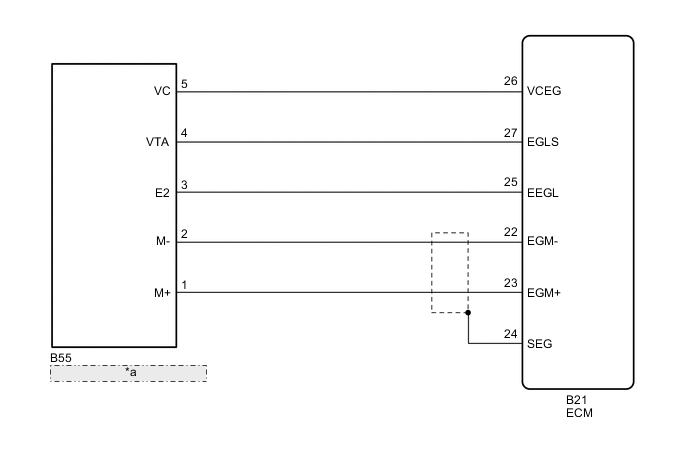
| *a | ELECTRIC EGR VALVE ASSEMBLY |
CAUTION / NOTICE / HINT
Note
When replacing the ECM, the ECM needs Registration and Initialization Click here.
Tech Tips
When the ECM must be replaced, before replacing the ECM, perform the "Learning Values Save" function using the intelligent tester. Then after installing the new ECM, perform all of the initialization/registrations for the "Learning Values Write" function by following the instructions shown on the tester display.
PROCEDURE
-
CHECK HARNESS AND CONNECTOR (ELECTRIC EGR VALVE ASSEMBLY - ECM)
-
Disconnect the electric EGR valve assembly connector.
-
Disconnect the ECM connector.
-
Measure the resistance according to the value(s) in the table below.
Standard Resistance (Check for Open) Tester Connection Condition Specified Condition B55-5 (VC) - B21-26 (VCEG) Always Below 1 Ω B55-4 (VTA) - B21-27 (EGLS) Always Below 1 Ω B55-3 (E2) - B21-25 (EEGL) Always Below 1 Ω Standard Resistance (Check for Short) Tester Connection Condition Specified Condition B55-5 (VC) or B21-26 (VCEG) - Body ground Always 10 kΩ or higher B55-4 (VTA) or B21-27 (EGLS) - Body ground Always 10 kΩ or higher B55-3 (E2) or B21-25 (EEGL) - Body ground Always 10 kΩ or higher -
Reconnect the electric EGR valve assembly connector.
-
Reconnect the ECM connector.
NG 
REPAIR OR REPLACE HARNESS OR CONNECTOR Click here
OK 
-
-
CHECK ECM TERMINAL VOLTAGE (VC TERMINAL)
-
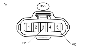
Text in Illustration *a Front view of wire harness connector
(to Electric EGR Valve Assembly)
Disconnect the electric EGR valve assembly connector.
-
Turn the ignition switch to ON.
-
Measure the voltage according to the value(s) in the table below.
Standard Voltage Tester Connection Switch Condition Specified Condition B55-5 (VC) - B55-3 (E2) Ignition switch ON 4.5 to 5.5 V -
Reconnect the electric EGR valve assembly connector.
NG
REPLACE ECM Click here
OK
-
-
REPLACE ELECTRIC EGR CONTROL VALVE ASSEMBLY
-
Replace electric EGR valve assembly Click here.
-
Turn the ignition switch to ON.
-
Turn the ignition switch off and wait for 30 seconds or more.
NEXT
CHECK WHETHER DTC OUTPUT RECURS (DTC P0405 OR P0406) Click here
-
-
REPAIR OR REPLACE HARNESS OR CONNECTOR
NEXT
-
CHECK WHETHER DTC OUTPUT RECURS (DTC P0405 OR P0406)
-
Connect the intelligent tester to the DLC3.
-
Turn the ignition switch to ON and turn the tester on.
-
Clear the DTCs Click here.
-
Turn the ignition switch to ON and wait for 15 seconds or more.
-
Enter the following menus: Powertrain / Engine and ECT / DTC.
-
Read the DTCs.
Result Result Proceed to No DTC output A DTC P0405 or P0406 B
A 
END
B
-
-
REPLACE ECM
-
Replace the ECM Click here.
NEXT
-
-
CONFIRM WHETHER MALFUNCTION HAS BEEN SUCCESSFULLY REPAIRED
-
Connect the intelligent tester to the DLC3.
-
Clear the DTCs Click here.
-
Turn the ignition switch to ON and wait for 15 seconds or more.
-
Enter the following menus: Powertrain / Engine and ECT / DTC.
-
Confirm that the DTC is not output again.
NEXT
END
-