RELAY ON-VEHICLE INSPECTION
PROCEDURE
-
INSPECT H-LP/US-DRL RELAY
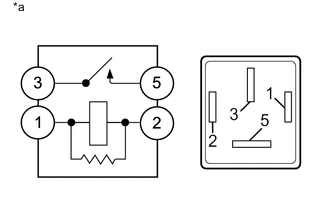
Text in Illustration *a Component without harness connected
(H-LP/US-DRL Relay)
-
Remove the H-LP/US-DRL relay from the engine room sub relay block.
-
Measure the resistance according to the value(s) in the table below.
Standard Resistance Tester Connection Condition Specified Condition 3 - 5 Voltage is not applied between terminal 1 and 2 10 kΩ or higher Voltage is applied between terminal 1 and 2 Below 1 Ω If the result is not as specified, replace the H-LP/US-DRL relay.
-
-
INSPECT DIM RELAY
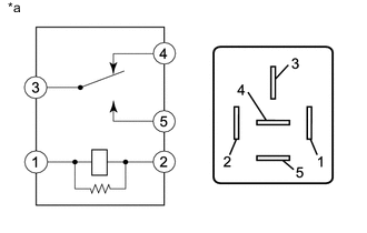
Text in Illustration *a Component without harness connected
(DIM Relay)
-
Remove the DIM relay from the engine room sub relay block.
-
Measure the resistance according to the value(s) in the table below.
Standard Resistance Tester Connection Condition Specified Condition 3 - 4 Battery voltage not applied to terminal 1 and 2 Below 1 Ω Battery voltage applied to terminal 1 and 2 10 kΩ or higher 3 - 5 Battery voltage not applied to terminal 1 and 2 10 kΩ or higher Battery voltage applied to terminal 1 and 2 Below 1 Ω If the result is not as specified, replace the DIM relay.
-
-
INSPECT FR FOG RELAY
Text in Illustration *a Component without harness connected
(FR FOG Relay)
-
Remove the FR FOG relay from the No. 5 relay block.
-
Measure the resistance according to the value(s) in the table below.
Standard Resistance Tester Connection Condition Specified Condition 3 - 5 Battery voltage not applied to terminal 1 and 2 10 kΩ or higher Battery voltage applied to terminal 1 and 2 Below 1 Ω If the result is not as specified, replace the FR FOG relay.
-
-
INSPECT DRL RELAY
Text in Illustration *a Component without harness connected
(DRL Relay)
-
Remove the DRL relay from the No. 2 engine room relay block.
-
Measure the resistance according to the value(s) in the table below.
Standard Resistance Tester Connection Condition Specified Condition 3 - 5 Voltage is not applied between terminal 1 and 2 10 kΩ or higher Voltage is applied between terminal 1 and 2 Below 1 Ω If the result is not as specified, replace the DRL relay.
-