STOP LIGHT SWITCH INSTALLATION
PROCEDURE
-
INSTALL STOP LIGHT SWITCH MOUNTING ADJUSTER
-
Engage the 2 claws to install a new stop light switch mounting adjuster onto the brake pedal support sub-assembly.
-
-
INSTALL STOP LIGHT SWITCH ASSEMBLY
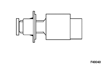
Text in illustration *1 Brake pedal *2 Stop Light Switch Mounting Adjuster *3 Stop light switch assembly
-
Install the stop light switch into the stop light switch mounting adjuster until it slightly touches the brake pedal.
Note
Do not depress the brake pedal.
-
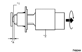
Text in illustration *1 Shaft *2 0.5 to 2.6 mm *a Stop light switch assembly Make a quarter turn clockwise to install the stop light switch.
Note
Do not depress the brake pedal.
- Torque:
- 1.5 N*m { 15 kgf*cm, 13 in.*lbf }
- or less
-
-
Check the stop light switch clearance.
Stop light switch clearance 0.5 to 2.6 mm (0.020 to 0.102 in.) -
Connect the stop light switch connector to the stop light switch.
-
-
INSTALL LOWER INSTRUMENT PANEL FINISH PANEL SUB-ASSEMBLY (w/o Knee Airbag)
-
INSTALL INSTRUMENT PANEL UNDER TRAY (w/o Knee Airbag)
-
INSTALL NO. 1 INSTRUMENT PANEL UNDER COVER SUB-ASSEMBLY (w/o Knee Airbag)
-
INSTALL NO. 1 INSTRUMENT PANEL LOWER AIR BAG ASSEMBLY (w/ Knee Airbag)
-
CONNECT CABLE TO NEGATIVE BATTERY TERMINAL
- Torque:
- 5.4 N*m { 55 kgf*cm, 48 in.*lbf }