HEADLIGHT LEVELING SWITCH INSPECTION
PROCEDURE
-
INSPECT HEADLIGHT LEVELING SWITCH
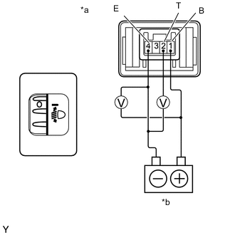
Text in Illustration *a Component without harness connected
(Headlight leveling switch)
*b Battery
-
Check the ratio.
-
Remove the head light leveling switch assembly.
-
Connect the positive (+) battery lead to terminal 1 and the negative (-) battery lead to terminal 4.
-
Check the ratio which is obtained by dividing the voltage between terminals 2 and 4 by the voltage between 1 and 4. The voltages must be measured using a voltmeter.
Standard Ratio Tester Connection Switch Condition Specified Condition 1 (B) - 4 (E)
2 (T) - 4 (E)
0 0.87 to 0.93 1 (B) - 4 (E)
2 (T) - 4 (E)
1 0.76 to 0.82 1 (B) - 4 (E)
2 (T) - 4 (E)
2 0.66 to 0.72 1 (B) - 4 (E)
2 (T) - 4 (E)
3 0.55 to 0.61 1 (B) - 4 (E)
2 (T) - 4 (E)
4 0.44 to 0.50 1 (B) - 4 (E)
2 (T) - 4 (E)
5 0.34 to 0.40 If the result is not as specified, replace the headlight leveling switch.
-
-
Check the illumination operation.
-
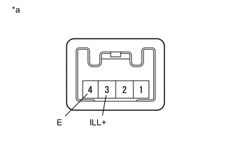
Text in Illustration *a Component without harness connected
(Headlight leveling switch)
Apply battery voltage to the head light leveling switch assembly connector.
Standard Tester Connection Specified Condition Battery positive (+) →Terminal 3 (ILL+)
Battery positive (-) →Terminal 4 (E)
The illumination comes on If the illumination does not illuminate, replace the headlight leveling switch.
-
-