LIGHTING SYSTEM TERMINALS OF ECU

-
CHECK INSTRUMENT PANEL JUNCTION BLOCK ASSEMBLY AND MAIN BODY ECU (MULTIPLEX NETWORK BODY ECU) (w/o Theft Deterrent System)
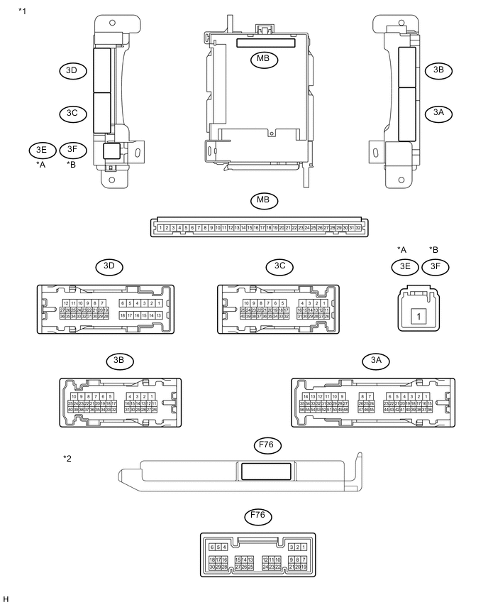
Text in Illustration *A for LHD *B for RHD *1 Instrument Panel Junction Block Assembly *2 Main Body ECU (Multiplex Network Body ECU)
-
Disconnect the 3A, 3B, 3C and 3E*1 or 3F*2 instrument panel junction block assembly connectors.
-
*1: for LHD
-
*2: for RHD
-
-
Measure the voltage and resistance according to the value(s) in the table below.
Standard Voltage Terminal No. (Symbol) Wiring Color Terminal Description Condition Specified Condition 3E-1*1 - Body ground Body ground B - Body ground Battery power supply Always 11 to 14 V 3F-1*2 - Body ground - Body ground B - Body ground Battery power supply Always 11 to 14 V
-
*1: for LHD
-
*2: for RHD
Standard Resistance Terminal No. (Symbol) Wiring Color Terminal Description Condition Specified Condition 3B-8 - Body ground W-B - Body ground Ground Always Below 1 Ω Tech Tips
If the result is not as specified, there may be a malfunction in the wire harness.
-
-
Reconnect the 3A, 3B, 3C and 3E*1 or 3F*2 instrument panel junction block assembly connectors.
-
*1: for LHD
-
*2: for RHD
-
-
Measure the resistance according to the value(s) in the table below.
Standard Resistance Terminal No. (Symbol) Wiring Color Terminal Description Condition Specified Condition F76-22 (CLTE)* - Body ground G - Body ground Automatic light control sensor ground Always Below 1 Ω
-
*: w/ Automatic Light Control System
-
-
Measure the voltage or check for pulses according to the value(s) in the table below.
Terminal No. (Symbol) Wiring Color Terminal Description Condition Specified Condition F76-1 (RFOG)*1 - Body ground LG - Body ground Rear fog light switch signal Rear fog light switch on Below 1 V Rear fog light switch off 11 to 14 V F76-5 (HU)*2 - Body ground P - Body ground Dimmer switch high signal Dimmer switch in high position Below 1 V Dimmer switch in low position 11 to 14 V F76-8 (HF)*2 - Body ground P - Body ground Dimmer switch high flash signal Dimmer switch in high flash position Below 1 V Dimmer switch not in high flash position 11 to 14 V F76-15 (DRLE)*1 - Body ground L - Body ground Daytime running light system drive output Daytime running light system operating Below 1 V Daytime running light system not operating 11 to 14 V F76-20 (CLTB)*3 - Body ground W - Body ground Automatic light control sensor power supply Ignition switch ON 11 to 14 V F76-21 (CLTS)*3 - Body ground B - Body ground Automatic light control sensor signal Ignition switch off Below 1 V Automatic light control system operates Pulse generation
(See waveform 1)
F76-27 (FFOG)*4 - Body ground G - Body ground Front fog light switch signal Front fog light switch on Below 1 V Front fog light switch off 11 to 14 V F76-28 (A)*3 - Body ground V - Body ground Light control switch AUTO signal Light control switch in AUTO position Below 1 V Light control switch not in AUTO position 11 to 14 V*5 Pulse generation*1 F76-29 (HEAD)*2 - Body ground L - Body ground Light control switch head signal Light control switch in head position Below 1 V Light control switch not in head position 11 to 14 V F76-30 (TAIL)*2 - Body ground) SB - Body ground Light control switch tail signal Light control switch in tail or head position Below 1 V Light control switch in neither tail nor head position 11 to 14 V 3A-15*4 - Body ground P - Body ground Front fog relay drive output Light control switch in tail and front fog light switch on Below 1 V Light control switch in tail and front fog light switch off 11 to 14 V 3A-28*1 - Body ground R - Body ground Parking brake switch signal Parking brake applied Below 1 V Parking brake released 11 to 14 V 3C-18 (HRLY)*2 - Body ground V - Body ground Headlight relay drive output Light control switch in head Below 1 V Light control switch not in head 11 to 14 V 3C-35 (DIM)*2 - Body ground P - Body ground Dimmer relay drive output Dimmer switch in high or high flash position Below 1 V Dimmer switch in low position 11 to 14 V
-
*1: w/ Rear Fog Light
-
*2: w/ Rear Fog Light or w/ Automatic Light Control System
-
*3: w/ Automatic Light Control System
-
*4: w/ Front Fog Light
-
*5: w/o Rear Fog Light
Tech Tips
If the result is not as specified, the main body ECU (multiplex network body ECU) may have a malfunction.
-
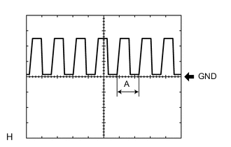
Waveform 1
Item Content Terminal No. (Symbol) F76-21 (CLTS) - Body ground Tool setting 5 V/DIV., 5 ms./DIV. Condition Ignition switch ON
Headlight dimmer switch AUTO
Automatic light control sensor covered with a hand → Automatic light control sensor exposed to ambient light
Tech Tips
If the ambient light becomes brighter, width A becomes narrower.
-
-
-
CHECK INSTRUMENT PANEL JUNCTION BLOCK ASSEMBLY AND MAIN BODY ECU (MULTIPLEX NETWORK BODY ECU) (w/ Theft Deterrent System)
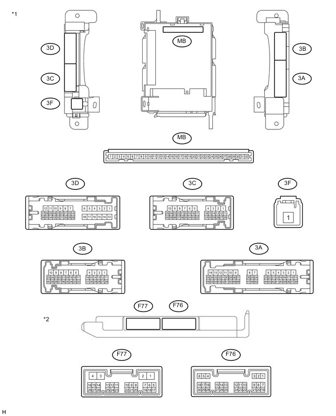
Text in Illustration *1 Instrument Panel Junction Block Assembly *2 Main Body ECU (Multiplex Network Body ECU)
-
Disconnect the 3A, 3B, 3C and 3F instrument panel junction block assembly connectors.
-
Measure the voltage and resistance according to the value(s) in the table below.
Standard Voltage Terminal No. (Symbol) Wiring Color Terminal Description Condition Specified Condition 3F-1 - Body ground - Body ground B - Body ground Battery power supply Always 11 to 14 V Standard Resistance Terminal No. (Symbol) Wiring Color Terminal Description Condition Specified Condition 3B-8 - Body ground W-B - Body ground Ground Always Below 1 Ω Tech Tips
If the result is not as specified, there may be a malfunction in the wire harness.
-
Reconnect the 3A, 3B, 3C and 3F instrument panel junction block assembly connectors.
-
Measure the resistance according to the value(s) in the table below.
Standard Resistance Terminal No. (Symbol) Wiring Color Terminal Description Condition Specified Condition F76-22 (CLTE)* - Body ground G - Body ground Automatic light control sensor ground Always Below 1 Ω
-
*: w/ Automatic Light Control System
-
-
Measure the voltage or check for pulses according to the value(s) in the table below.
Terminal No. (Symbol) Wiring Color Terminal Description Condition Specified Condition F76-1 (RFOG) - Body ground LG - Body ground Rear fog light switch signal Rear fog light switch on Below 1 V Rear fog light switch off 11 to 14 V F76-5 (HU) - Body ground P - Body ground Dimmer switch high signal Dimmer switch in high position Below 1 V Dimmer switch in low position 11 to 14 V F76-8 (HF) - Body ground P - Body ground Dimmer switch high flash signal Dimmer switch in high flash position Below 1 V Dimmer switch not in high flash position 11 to 14 V F76-15 (DRLE) - Body ground L - Body ground Daytime running light system drive output Daytime running light system operating Below 1 V Daytime running light system not operating 11 to 14 V F76-20 (CLTB)*1 - Body ground W - Body ground Automatic light control sensor power supply Ignition switch ON 11 to 14 V F76-21 (CLTS)*1 - Body ground B - Body ground Automatic light control sensor signal Ignition switch off Below 1 V Automatic light control system operates Pulse generation
(See waveform 1)
F76-27 (FFOG)*2 - Body ground G - Body ground Front fog light switch signal Front fog light switch on Below 1 V Front fog light switch off 11 to 14 V F76-28 (A)*1 - Body ground V - Body ground Light control switch AUTO signal Light control switch in AUTO position Below 1 V Light control switch not in AUTO position Pulse generation F76-29 (HEAD) - Body ground L - Body ground Light control switch head signal Light control switch in head position Below 1 V Light control switch not in head position 11 to 14 V F76-30 (TAIL) - Body ground) SB - Body ground Light control switch tail signal Light control switch in tail or head position Below 1 V Light control switch in neither tail nor head position 11 to 14 V 3A-15*2 - Body ground P - Body ground Front fog relay drive output Light control switch in tail and front fog light switch on Below 1 V Light control switch in tail and front fog light switch off 11 to 14 V 3A-28 - Body ground R - Body ground Parking brake switch signal Parking brake applied Below 1 V Parking brake released 11 to 14 V 3C-18 (HRLY) - Body ground V - Body ground Headlight relay drive output Light control switch in head Below 1 V Light control switch not in head 11 to 14 V 3C-35 (DIM) - Body ground P - Body ground Dimmer relay drive output Dimmer switch in high or high flash position Below 1 V Dimmer switch in low position 11 to 14 V
-
*1: w/ Automatic Light Control System
-
*2: w/ Front Fog Light
Tech Tips
If the result is not as specified, the main body ECU (multiplex network body ECU) may have a malfunction.
-
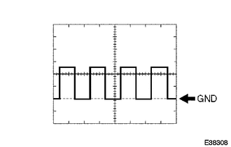
Waveform 1
Item Content Terminal No. (Symbol) F76-21 (CLTS) - Body ground Tool setting 5 V/DIV., 5 ms./DIV. Condition Ignition switch ON
Headlight dimmer switch AUTO
Automatic light control sensor covered with a hand → Automatic light control sensor exposed to ambient light
Tech Tips
If the ambient light becomes brighter, width A becomes narrower.
-
-
-
CHECK HEADLIGHT LEVELING ECU ASSEMBLY (w/ HID Headlight)

-
Disconnect the A43 headlight leveling ECU assembly connector.
-
Measure the voltage and resistance according to the value(s) in the table below.
Standard Voltage Terminal No. (Symbol) Wiring Color Terminal Description Condition Specified Condition A43-1 (IG) - Body ground V - Body ground Ignition power supply Ignition switch off Below 1 V Ignition switch ON 11 to 14 V Standard Resistance Terminal No. (Symbol) Wiring Color Terminal Description Condition Specified Condition A43-9 (E1) - Body ground W-B - Body ground Ground Always Below 1 Ω Tech Tips
If the result is not as specified, there may be a malfunction on the wire harness side.
-
Reconnect the A43 headlight leveling ECU assembly connector.
-
Measure the resistance and voltage according to the value(s) in the table below.
Terminal No. (Symbol) Wiring Color Terminal Description Condition Specified Condition A43-3 (HDLP) - A43-9 (E1) BE - W-B Low beam headlight signal input Low beam headlights on Below 1.5 V Low beam headlights off Above 5 V A43-5 (INIT) - A43-9 (E1) G - W-B Initialization signal input Terminal LVL and terminal GND of DLC3 connected Below 1 V Terminal LVL and terminal GND of DLC3 not connected Approx. 5 V A43-6 (WNG) - A43-9 (E1) SB - W-B Warning indicator drive output Warning indicator on Below 1 V Warning indicator off 11 to 14 V A43-10 (RH+) - A43-9 (E1) R - W-B Leveling motor RH power supply Ignition switch off Below 1 V Ignition switch ON 11 to 14 V A43-11 (LH+) - A43-9 (E1) G - W-B Leveling motor LH power supply Ignition switch off Below 1 V Ignition switch ON 11 to 14 V A43-12 (SBR) - A43-21 (SGR) P - R Rear height control sensor power supply Ignition switch off Below 1 V Ignition switch ON 4.75 to 5.25 V A43-16 (SPDR) - A43-9 (E1) GR - W-B Vehicle speed signal input Vehicle is driven at approx. 20 km/h (12 mph) Pulse generation
(See waveform 1)
A43-17 (RHT) - A43-9 (E1) G - W-B Leveling motor RH operation signal input With low beam headlights on, vehicle height not changed Below 1 V With low beam headlights on, vehicle height changed and maintained for more than 3 seconds 1.0 to 14.4 V A43-18 (LHT) - A43-9 (E1) R - W-B Leveling motor LH operation signal input With low beam headlights on, vehicle height not changed Below 1 V With low beam headlights on, vehicle height changed and maintained for more than 3 seconds 1.0 to 14.4 V A43-19 (SHRL) - A43-21 (SGR) G - R Rear height control sensor signal input Ignition switch off Below 1 V Ignition switch ON 0.5 to 4.5 V A43-21 (SGR) - A43-9 (E1) R - W-B Rear height control sensor ground Always Below 1 Ω A43-23 (RH-) - A43-9 (E1) L - W-B Leveling motor RH ground Always Below 1 Ω A43-24 (LH-) - A43-9 (E1) L - W-B Leveling motor LH ground Always Below 1 Ω Tech Tips
If the result is not as specified, the ECU may have a malfunction.
-
Waveform 1
Item Content Terminal No. (Symbol) A43-16 (SPDR) - A43-9 (E1) Tool setting 2 V/DIV., 2 ms./DIV. Condition Vehicle is driven at approx. 20 km/h (12 mph)
-
-
-
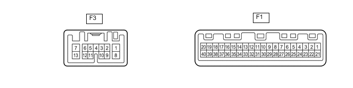
CHECK COMBINATION METER ASSEMBLY
-
Disconnect the F1 and F3 combination meter assembly connectors.
-
Measure the resistance and voltage and resistance according to the value(s) in the table below.
Standard Voltage Terminal No. (Symbol) Wiring Color Terminal Description Condition Specified Condition F3-1 (B) - Body ground R - Body ground Battery power supply Always 11 to 14 V Standard Resistance Terminal No. (Symbol) Wiring Color Terminal Description Condition Specified Condition F1-21 (ET) - Body ground W-B - Body ground Ground Always Below 1 Ω Tech Tips
If the result is not as specified, there may be a malfunction on the wire harness side.
-
Reconnect the F1 and F3 combination meter assembly connectors.
-
Measure the resistance and voltage according to the value(s) in the table below.
Terminal No. (Symbol) Wiring Color Terminal Description Condition Specified Condition F3-3 (HAZ) - Body ground L - Body ground Hazard warning signal switch signal Hazard warning signal switch off 11 to 14 V Hazard warning signal switch on Below 1 Ω F3-7 (LR) - Body ground V - Body ground Turn signal light RH drive output Turn signal light RH turned on 11 to 14 V Turn signal light RH turned off Below 1 Ω F3-9 (ER) - Body ground B - Body ground Turn signal switch RH signal Turn signal switch RH on Below 1 Ω Turn signal switch RH off 11 to 14 V F3-10 (EL) - Body ground Y - Body ground Turn signal switch LH signal Turn signal switch LH on Below 1 Ω Turn signal switch LH off 11 to 14 V F3-13 (LL) - Body ground LG - Body ground Turn signal light LH drive output Turn signal light LH turned on 11 to 14 V Turn signal light LH turned off Below 1 Ω Tech Tips
If the result is not as specified, the ECU may have a malfunction.
-