LIGHTING SYSTEM Stop Light Circuit
DESCRIPTION
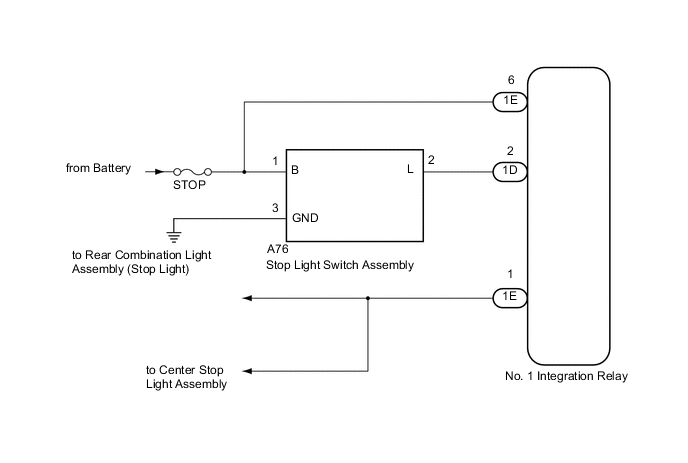
When the stop light switch is turned on, current flows to the stop lights to illuminate them.
WIRING DIAGRAM
CAUTION / NOTICE / HINT
Note
Inspect the fuses and bulbs for circuits related to this system before performing the following inspection procedure.
PROCEDURE
-
INSPECT STOP LIGHT SWITCH ASSEMBLY
-
Inspect the stop light switch assembly Click here.
NG 
REPLACE STOP LIGHT SWITCH ASSEMBLY Click here
OK 
-
-
CHECK HARNESS AND CONNECTOR (BATTERY - STOP LIGHT SWITCH ASSEMBLY)
-
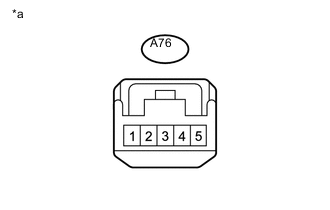
Text in Illustration *a Front view of wire harness connector
(to stop light switch assembly)
Measure the voltage according to the value(s) in the table below.
Standard Voltage Tester Connection Condition Specified Condition A76-1 (B)- Body ground Always 11 to 14 V
NG
REPAIR OR REPLACE HARNESS OR CONNECTOR
OK
-
-
CHECK HARNESS AND CONNECTOR (STOP LIGHT SWITCH ASSEMBLY - BODY GROUND)
-
Measure the resistance according to the value(s) in the table below.
Standard Resistance (Check for Open) Tester Connection Condition Specified Condition A76-3 (GND) - Body Ground Always Below 1 Ω
NG
REPAIR OR REPLACE HARNESS OR CONNECTOR
OK
-
-
CHECK HARNESS AND CONNECTOR (NO. 1 INTEGRATION RELAY - BATTERY, STOP LIGHT SWITCH)
-
Remove the No. 1 integration relay Click here.
-
Measure the resistance according to the value(s) in the table below.
Standard Resistance (Check for Open) Tester Connection Condition Specified Condition A76-2 (L) - 1D-2 Always Below 1 Ω Standard Resistance (Check for Short) Tester Connection Condition Specified Condition A76-2 (L) - Body ground Always 10 kΩ or higher -
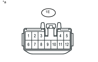
Text in Illustration *a Front view of wire harness connector
(to No. 1 integration relay)
Measure the voltage according to the value(s) in the table below.
Standard Voltage Tester Connection Condition Specified Condition 1E-6 - Body ground Always 11 to 14 V
OK
PROCEED TO NEXT SUSPECTED AREA SHOWN IN PROBLEM SYMPTOMS TABLE Click here
NG
REPAIR OR REPLACE HARNESS OR CONNECTOR
-