LIGHTING SYSTEM Daytime Running Light Relay Circuit
DESCRIPTION
The main body ECU (multiplex network body ECU) controls the daytime running lights.
WIRING DIAGRAM
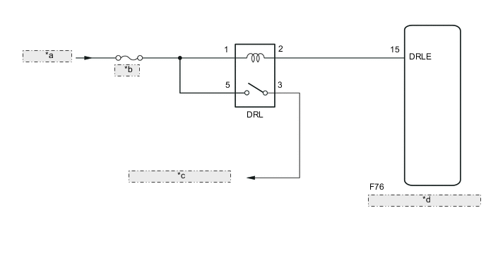
| *a | from Battery |
| *b | EU-DRL |
| *c | to Daytime Running Lights |
| *d | Main Body ECU (Multiplex Network Body ECU) |
CAUTION / NOTICE / HINT
Note
-
Inspect the fuses for circuits related to this system before performing the following inspection procedure.
-
Initialization is necessary when the main body ECU (multiplex network body ECU) is replaced Click here.*
Note
-
*: w/ Automatic Light Control System
PROCEDURE
-
INSPECT DRL Relay
-
Remove the DRL relay from the No. 2 engine room relay block.
-
Inspect the DRL relay Click here.
NG 
REPLACE DRL RELAY
OK 
-
-
CHECK HARNESS AND CONNECTOR (DRL RELAY - BATTERY)
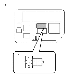
Text in Illustration *1 No. 2 Engine Room Relay Block *a DRL Relay Terminal
-
Remove the DRL relay from the No. 2 engine room relay block.
-
Measure the voltage according to the value(s) in the table below.
Standard Voltage Tester Connection Condition Specified Condition Relay terminal 1 - Body ground Always 11 to 14 V Relay terminal 5 - Body ground Always 11 to 14 V
NG
REPAIR OR REPLACE HARNESS OR CONNECTOR
OK
-
-
CHECK HARNESS AND CONNECTOR (DRL RELAY - MAIN BODY ECU (MULTIPLEX NETWORK BODY ECU))
-
Remove the DRL relay from the No. 2 engine room relay block.
-
Disconnect the F76 Main Body ECU (multiplex network body ECU) connector.
-
Measure the resistance according to the value(s) in the table below.
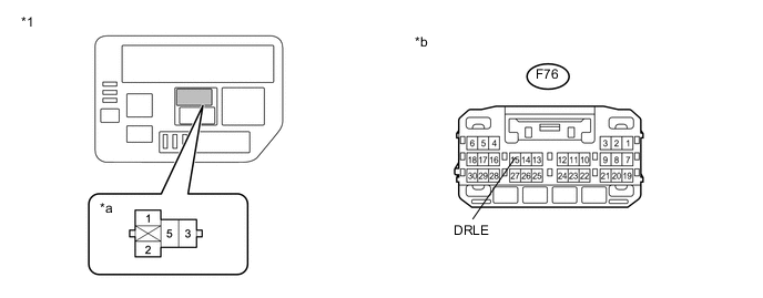
Text in Illustration *1 No. 2 Engine Room Relay Block - - *a H-LP/US-DRL Relay Terminal *b Front view of wire harness connector
(to Main Body ECU (Multiplex Network Body ECU))
Standard Resistance (Check for Open) Tester Connection Condition Specified Condition Relay terminal 2 - F76-15 (DRLE) Always Below 1 Ω Standard Resistance (Check for Short) Tester Connection Condition Specified Condition Relay terminal 2 - Body ground Always 10 kΩ or higher
OK
PROCEED TO NEXT SUSPECTED AREA SHOWN IN PROBLEM SYMPTOMS TABLE Click here
NG
REPAIR OR REPLACE HARNESS OR CONNECTOR
-