LIGHTING SYSTEM Headlight Relay Circuit
DESCRIPTION
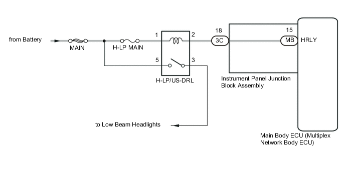
The main body ECU (multiplex network body ECU) receives headlight dimmer switch information signals, and illuminates the headlight.
WIRING DIAGRAM
CAUTION / NOTICE / HINT
Note
-
Inspect the fuses and bulbs for circuits related to this system before performing the following inspection procedure.
-
Initialization is necessary when the main body ECU (multiplex network body ECU) is replaced Click here.*
-
*: w/ Automatic Light Control System
PROCEDURE
-
PERFORM ACTIVE TEST USING INTELLIGENT TESTER (HEADLIGHT RELAY)
-
Using the intelligent tester, perform the Active Test Click here.
Main Body Tester Display Test Part Control Range Diagnostic Note Headlight Relay Low beam headlight relay ON/OFF - OK Headlight relay operates (low beam headlights illuminate). Result Result Proceed to NG A OK B
B 
REPLACE MAIN BODY ECU (MULTIPLEX NETWORK BODY ECU) Click here
A 
-
-
INSPECT HEADLIGHT RELAY (H-LP/US-DRL)
-
Remove the headlight relay (H-LP/US-DRL) from the No. 2 engine room relay block.
-
Inspect the headlight relay (H-LP/US-DRL) Click here.
NG
REPLACE HEADLIGHT RELAY (H-LP/US-DRL)
OK
-
-
CHECK HARNESS AND CONNECTOR (HEADLIGHT RELAY - BATTERY)
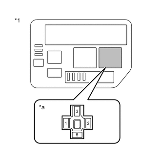
Text in Illustration *1 No. 2 Engine Room Relay Block *a H-LP/US-DRL Relay Terminal
-
Remove the headlight relay (H-LP/US-DRL) from the No. 2 engine room relay block.
-
Measure the voltage according to the value(s) in the table below.
Standard Voltage Tester Connection Condition Specified Condition Relay terminal 1 - Body ground Always 11 to 14 V Relay terminal 5 - Body ground Always 11 to 14 V
NG
REPAIR OR REPLACE HARNESS OR CONNECTOR
OK
-
-
CHECK HARNESS AND CONNECTOR (HEADLIGHT RELAY - INSTRUMENT PANEL JUNCTION BLOCK)
-
Remove the headlight relay (H-LP/US-DRL) from the No. 2 engine room relay block.
-
Disconnect the 3C instrument panel junction block assembly connector.
-
Measure the resistance according to the value(s) in the table below.
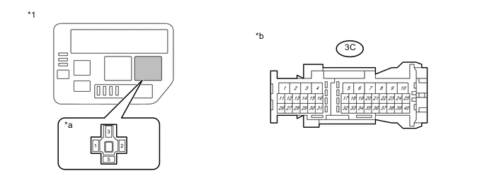
Text in Illustration *1 No. 2 Engine Room Relay Block - - *a H-LP/US-DRL Relay Terminal *b Front view of wire harness connector
(to Instrument Panel Junction Block Assembly)
Standard Resistance (Check for Open) Tester Connection Condition Specified Condition Relay terminal 2 - 3C-18 Always Below 1 Ω Standard Resistance (Check for Short) Tester Connection Condition Specified Condition 3C-18 - Body ground Always 10 kΩ or higher
NG
REPAIR OR REPLACE HARNESS OR CONNECTOR
OK
-
-
INSPECT INSTRUMENT PANEL JUNCTION BLOCK ASSEMBLY
-
Remove the instrument panel junction block assembly Click here.
-
Remove the main body ECU (multiplex network body ECU) from the instrument panel junction block assembly.
-
Measure the resistance according to the value(s) in the table below.
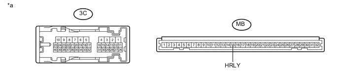
Text in Illustration *a Component without harness connected
(Instrument Panel Junction Block Assembly)
- - Standard Resistance Tester Connection Condition Specified Condition 3C-18 - MB-15 (HRLY) Always Below 1 Ω
OK
PROCEED TO NEXT SUSPECTED AREA SHOWN IN PROBLEM SYMPTOMS TABLE Click here
NG
REPLACE INSTRUMENT PANEL JUNCTION BLOCK ASSEMBLY Click here
-