LIGHTING SYSTEM Headlight Relay Circuit
DESCRIPTION
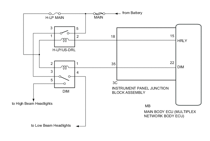
The main body ECU (multiplex network body ECU) receives headlight dimmer switch information signals, and illuminates the low beam headlight or high beam headlight.
WIRING DIAGRAM
CAUTION / NOTICE / HINT
Tech Tips
Inspect the fuses and bulbs for circuits related to this system before performing the following inspection procedure.
Note
Initialization is necessary when the main body ECU (multiplex network body ECU) is replaced Click here.*
-
*: w/ Automatic Light Control System
PROCEDURE
-
CHECK VEHICLE CONDITION
-
Check the illuminating condition of the low beam and high beam headlights.
Result Result Proceed to Low beam headlights do not illuminate.
(High beam headlights are normal.)
A High beam headlights do not illuminate.
(Low beam headlights are normal.)
B Low beam headlights and high beam headlights do not illuminate. C
B 
INSPECT HEADLIGHT DIMMER RELAY (DIM) Click here
C
INSPECT HEADLIGHT RELAY (H-LP/US-DRL) Click here
A 
-
-
INSPECT HEADLIGHT DIMMER RELAY (DIM)
-
Remove the headlight dimmer relay from the No. 2 engine room relay block.
-
Inspect the headlight dimmer relay Click here.
OK 
PROCEED TO NEXT SUSPECTED AREA SHOWN IN PROBLEM SYMPTOMS TABLE Click here
NG
REPLACE HEADLIGHT DIMMER RELAY
-
-
INSPECT HEADLIGHT DIMMER RELAY (DIM)
-
Remove the headlight dimmer relay from the No. 2 engine room relay block.
-
Inspect the headlight dimmer relay Click here.
NG
REPLACE HEADLIGHT DIMMER RELAY
OK
-
-
CHECK HARNESS AND CONNECTOR (BATTERY - DIMMER RELAY)
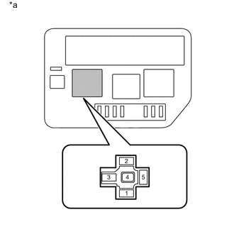
Text in Illustration *a No. 2 Engine Room Relay Block
(DIM Relay Terminal)
-
Measure the voltage according to the value(s) in the table below.
Standard Voltage Tester Connection Condition Specified Condition Relay terminal 2 - Body ground Always 11 to 14 V
NG
REPAIR OR REPLACE HARNESS OR CONNECTOR
OK
-
-
CHECK HARNESS AND CONNECTOR (DIMMER RELAY - INSTRUMENT PANEL JUNCTION BLOCK)
-
Disconnect the 3C instrument panel junction block assembly connector.
-
Measure the resistance according to the value(s) in the table below.
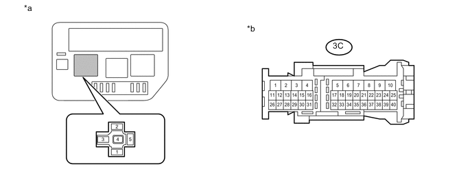
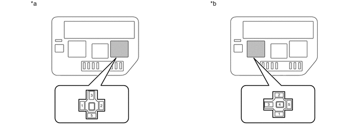
Text in Illustration *a No. 2 Engine Room Relay Block
(DIM Relay Terminal)
*b Front view of wire harness connector
(to Instrument Panel Junction Block Assembly)
Standard Resistance (Check for Open) Tester Connection Condition Specified Condition Relay terminal 1 - 3C-35 Always Below 1 Ω Standard Resistance (Check for Short) Tester Connection Condition Specified Condition 3C-35 - Body ground Always 10 kΩ or higher
NG
REPAIR OR REPLACE HARNESS OR CONNECTOR
OK
-
-
INSPECT INSTRUMENT PANEL JUNCTION BLOCK ASSEMBLY
-
Remove the instrument panel junction block assembly Click here.
-
Remove the main body ECU (multiplex network body ECU) from the instrument panel junction block assembly.
-
Measure the resistance according to the value(s) in the table below.
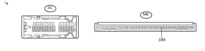
Text in Illustration *a Component without harness connected
(Instrument Panel Junction Block Assembly)
- - Standard Resistance Tester Connection Condition Specified Condition 3C-35 - MB-22 (DIM) Always Below 1 Ω
OK
PROCEED TO NEXT SUSPECTED AREA SHOWN IN PROBLEM SYMPTOMS TABLE Click here
NG
REPLACE INSTRUMENT PANEL JUNCTION BLOCK ASSEMBLY Click here
-
-
INSPECT HEADLIGHT RELAY (H-LP/US-DRL)
-
Remove the headlight relay from the No. 2 engine room relay block.
-
Inspect the headlight relay Click here.
NG
REPLACE HEADLIGHT RELAY
OK
-
-
INSPECT HEADLIGHT DIMMER RELAY (DIM)
-
Remove the headlight dimmer relay from the No. 2 engine room relay block.
-
Inspect the headlight dimmer relay Click here.
NG
REPLACE HEADLIGHT DIMMER RELAY
OK
-
-
CHECK HARNESS AND CONNECTOR (BATTERY - HEADLIGHT RELAY, DIMMER RELAY)
-
Measure the voltage according to the value(s) in the table below.
Text in Illustration *a No. 2 Engine Room Relay Block
(H-LP/US-DRL Relay Terminal)
*b No. 2 Engine Room Relay Block
(DIM Relay Terminal)
Standard Voltage H-LP/US-DRL Relay Terminal Tester Connection Condition Specified Condition Relay Terminal 1 - Body Ground Always 11 to 14 V Relay Terminal 5 - Body Ground Always 11 to 14 V DIM Relay Terminal Tester Connection Condition Specified Condition Relay Terminal 2 - Body Ground Always 11 to 14 V
NG
REPAIR OR REPLACE HARNESS OR CONNECTOR
OK
-
-
CHECK HARNESS AND CONNECTOR (HEADLIGHT RELAY - DIMMER RELAY)
-
Measure the resistance according to the value(s) in the table below.
Text in Illustration *a No. 2 Engine Room Relay Block
(H-LP/US-DRL Relay Terminal)
*b No. 2 Engine Room Relay Block
(DIM Relay Terminal)
Standard Resistance (Check for Open) Tester Connection Condition Specified Condition H-LP/US-DRL Relay Terminal 3 - DIM Relay Terminal 3 Always Below 1 Ω Standard Resistance (Check for Short) Tester Connection Condition Specified Condition H-LP/US-DRL Relay Terminal 3 - Body Ground Always 10 kΩ or higher
NG
REPAIR OR REPLACE HARNESS OR CONNECTOR
OK
-
-
CHECK HARNESS AND CONNECTOR (INSTRUMENT PANEL JUNCTION BLOCK - HEADLIGHT RELAY, DIMMER RELAY)
-
Disconnect the 3C instrument panel junction block assembly connector.
-
Measure the resistance according to the value(s) in the table below.
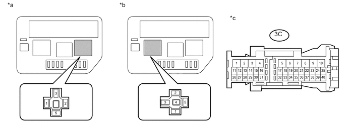
Text in Illustration *a No. 2 Engine Room Relay Block
(H-LP/US-DRL Relay Terminal)
*b No. 2 Engine Room Relay Block
(DIM Relay Terminal)
*c Front view of wire harness connector
(to Instrument Panel Junction Block Assembly)
- - Standard Resistance (Check for Open) Tester Connection Condition Specified Condition H-LP/US-DRL Relay Terminal 2 - 3C-18 Always Below 1 Ω DIM Relay Terminal 1 - 3C-35 Always Below 1 Ω Standard Resistance (Check for Short) Tester Connection Condition Specified Condition 3C-18 - Body ground Always 10 kΩ or higher 3C-35 - Body ground Always 10 kΩ or higher
NG
REPAIR OR REPLACE HARNESS OR CONNECTOR
OK
-
-
INSPECT INSTRUMENT PANEL JUNCTION BLOCK ASSEMBLY
-
Remove the instrument panel junction block assembly Click here.
-
Remove the main body ECU (multiplex network body ECU) from the instrument panel junction block assembly.
-
Measure the resistance according to the value(s) in the table below.
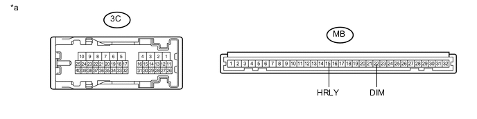
Text in Illustration *a Component without harness connected
(Instrument Panel Junction Block Assembly)
- - Standard Resistance Tester Connection Condition Specified Condition 3C-18 - MB-15 (HRLY) Always Below 1 Ω 3C-35 - MB-22 (DIM) Always Below 1 Ω
OK
PROCEED TO NEXT SUSPECTED AREA SHOWN IN PROBLEM SYMPTOMS TABLE Click here
NG
REPLACE INSTRUMENT PANEL JUNCTION BLOCK ASSEMBLY Click here
-