СИСТЕМА SFI Fuel Injector Circuit
Информация добавлена 08-08-2017 ![]()
DESCRIPTION
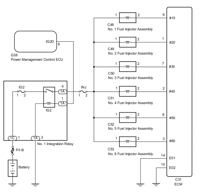
The fuel injector assemblies are located on the intake manifold. They inject fuel into the cylinders based on the signals from the ECM.
WIRING DIAGRAM
CAUTION / NOTICE / HINT
Note
Inspect the fuses for circuits related to this system before performing the following inspection procedure.
PROCEDURE
-
CHECK FUEL INJECTOR ASSEMBLY (POWER SOURCE)
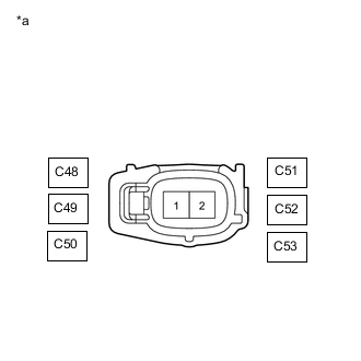
*a Front view of wire harness connector
(to Fuel Injector Assembly)
-
Disconnect the fuel injector assembly connector.
-
Measure the voltage according to the value(s) in the table below.
Standard Voltage Tester Connection Switch Condition Specified Condition C48-1 - Body ground Engine switch on (IG) 11 to 14 V C49-1 - Body ground Engine switch on (IG) 11 to 14 V C50-1 - Body ground Engine switch on (IG) 11 to 14 V C51-1 - Body ground Engine switch on (IG) 11 to 14 V C52-1 - Body ground Engine switch on (IG) 11 to 14 V C53-1 - Body ground Engine switch on (IG) 11 to 14 V -
Reconnect the fuel injector assembly connector.
Result Proceed to OK NG
NG 
INSPECT NO. 1 INTEGRATION RELAY (IG2) Click here
OK 
-
-
INSPECT FUEL INJECTOR ASSEMBLY
-
Inspect the fuel injector assembly.
Result Proceed to OK NG
NG 
REPLACE FUEL INJECTOR ASSEMBLY Click here
OK
-
-
CHECK HARNESS AND CONNECTOR (FUEL INJECTOR ASSEMBLY - ECM)
-
Disconnect the C48, C49, C50, C51, C52 and C53 fuel injector assembly connectors.
-
Disconnect the C31 ECM connector.
-
Measure the resistance according to the value(s) in the table below.
Standard Resistance Tester Connection Condition Specified Condition C48-2 - C31-6 (#10) Always Below 1 Ω C49-2 - C31-1 (#20) Always Below 1 Ω C50-2 - C31-7 (#30) Always Below 1 Ω C51-2 - C31-2 (#40) Always Below 1 Ω C52-2 - C31-8 (#50) Always Below 1 Ω C53-2 - C31-3 (#60) Always Below 1 Ω C48-2 or C31-6 (#10) - Body ground Always 10 kΩ or higher C49-2 or C31-1 (#20) - Body ground Always 10 kΩ or higher C50-2 or C31-7 (#30) - Body ground Always 10 kΩ or higher C51-2 or C31-2 (#40) - Body ground Always 10 kΩ or higher C52-2 or C31-8 (#50) - Body ground Always 10 kΩ or higher C53-2 or C31-3 (#60) - Body ground Always 10 kΩ or higher Result Proceed to OK NG
OK
REPLACE ECM Click here
NG
REPAIR OR REPLACE HARNESS OR CONNECTOR
-
-
INSPECT NO. 1 INTEGRATION RELAY (IG2)
-
Inspect the No. 1 integration relay (IG2).
Result Proceed to OK NG
OK
REPAIR OR REPLACE HARNESS OR CONNECTOR (NO. 1 INTEGRATION RELAY - FUEL INJECTOR ASSEMBLY)
NG
REPLACE NO. 1 INTEGRATION RELAY (IG2) Click here
-