АВТОМАТИЧЕСКАЯ ТРАНСМИССИЯ В СБОРЕ УСТАНОВКА
Информация добавлена 08-08-2017 ![]()
PROCEDURE
-
INSTALL TORQUE CONVERTER CLUTCH ASSEMBLY
-
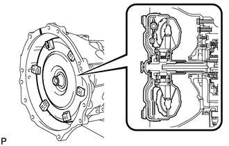
Attach the splines of the input shaft and turbine runner.
-
Attach the splines of the stator shaft and stator while turning the torque converter assembly.
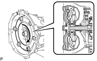
Tech Tips
If the stator shaft splines are difficult to engage with the stator splines, move the torque converter back approximately 10 mm (0.393 in.) and engage the splines while rotating the torque converter assembly.
-
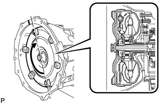
Turn the torque converter to engage the key of the oil pump drive gear with the slot on the torque converter assembly.
-
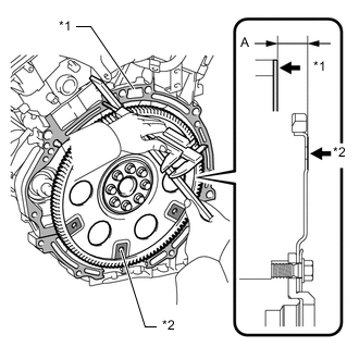
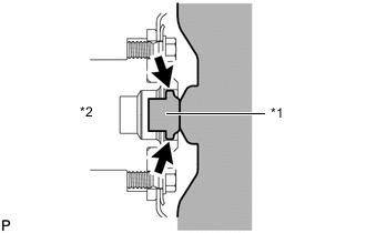
*1 Engine Surface *2 Drive Plate Surface Using a vernier caliper and straightedge, measure dimension A between the transmission contact surface of the engine and the torque converter contact surface of the drive plate.
-
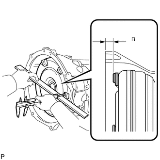
Using a vernier caliper and straightedge, measure dimension B shown in the illustration and check that dimension B is more than dimension A, which was measured in the previous step.
Standard distance B = A + 1 mm (0.0394 in.) or more Note
-
Make sure to deduct the thickness of the straightedge.
-
If the transaxle is installed to the engine with the torque converter not sufficiently inserted, the torque converter may be damaged.
-
-
-
INSTALL TRANSMISSION CONTROL CABLE BRACKET
-
Install the transmission control cable bracket to the transmission assembly with the 2 bolts.
- Torque:
- 14 N*m { 143 kgf*cm, 10 ft.*lbf }
-
-
INSTALL TRANSFER ASSEMBLY
-
INSTALL AUTOMATIC TRANSMISSION ASSEMBLY
-
*1 Torque Converter Centerpiece *2 Crankshaft Apply clutch spline grease to the circumference of the crankshaft contact surface with the torque converter centerpiece.
Clutch spline grease Toyota Genuine Clutch Spline Grease or equivalent Maximum grease amount Approximately 1 g (0.0353 oz.) -
Confirm that 2 knock pins are on the transmission contact surface of the engine block before transmission installation.
-
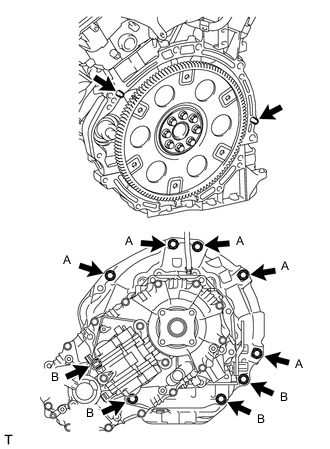
Install the automatic transmission assembly with the 9 bolts.
- Torque:
- for 17 mm head bolt A
- 71 N*m { 724 kgf*cm, 52 ft.*lbf }
- for 14 mm head bolt B
- 37 N*m { 377 kgf*cm, 27 ft.*lbf }
Note
Do not use excess force to pry on the automatic transmission assembly.
-
-
CONNECT BREATHER HOSE
-
Connect the 3 breather plug hoses to the engine.
-
-
CONNECT WIRE HARNESS AND CONNECTOR
-
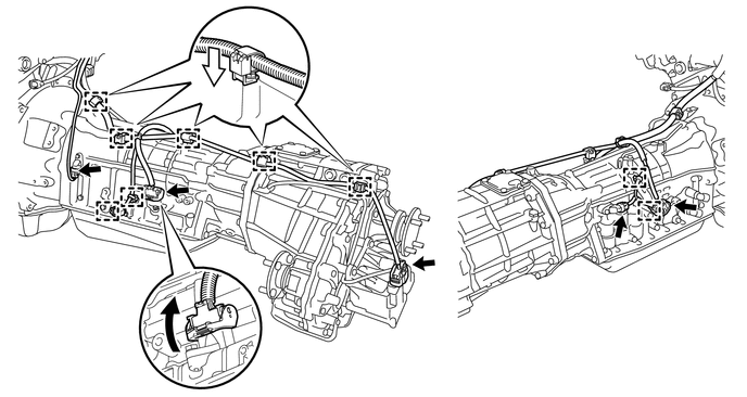
Connect the park/neutral position switch connector, transmission wire connector, 2 speed sensor connectors and transfer control side connector.
Tech Tips
Push up the lever until the claw of the transmission wire connector makes a connection sound.
-
Attach the 2 connector clamps and 7 harness clamps.
-
Tilt up the automatic transmission assembly.
-
-
INSTALL REAR NO. 1 ENGINE MOUNTING INSULATOR
-
Install the No. 1 rear engine mounting insulator to the automatic transmission assembly with the 4 bolts.
- Torque:
- 65 N*m { 663 kgf*cm, 48 ft.*lbf }
-
Install the No. 1 rear engine mounting heat insulator to the No. 1 rear engine mounting insulator with the bolt.
- Torque:
- 12 N*m { 122 kgf*cm, 9 ft.*lbf }
-
-
INSTALL NO. 3 FRAME CROSSMEMBER SUB-ASSEMBLY
-
Install the No. 3 frame crossmember sub-assembly with the 4 bolts and 4 nuts.
- Torque:
- 72 N*m { 734 kgf*cm, 53 ft.*lbf }
-
Install the No. 3 frame crossmember sub-assembly to the No. 1 rear engine mounting insulator with the 4 bolts.
- Torque:
- 30 N*m { 306 kgf*cm, 22 ft.*lbf }
-
-
INSTALL FRONT SUSPENSION MEMBER BRACKET LH AND RH
-
Install the front suspension member bracket LH and RH with the 8 bolts.
- Torque:
- 33 N*m { 337 kgf*cm, 24 ft.*lbf }
-
Disconnect the transmission jack.
-
-
INSTALL DRIVE PLATE AND TORQUE CONVERTER SETTING BOLT
-
Turn the crankshaft to gain access to the installation locations of the 6 drive plate and torque converter setting bolts and install each bolt while holding the crankshaft pulley bolt with a wrench.
- Torque:
- 48 N*m { 489 kgf*cm, 35 ft.*lbf }
Note
Install the black bolt first, and then the 5 silver bolts.
-
-
INSTALL TRANSFER CASE LOWER PROTECTOR
-
Install the transfer case lower protector with the 4 bolts.
- Torque:
- 18 N*m { 184 kgf*cm, 13 ft.*lbf }
-
-
CONNECT OIL COOLER TUBE ASSEMBLY
-
Install the oil cooler tube assembly with the 2 bolts.
- Torque:
- 14 N*m { 143 kgf*cm, 10 ft.*lbf }
-
-
INSTALL TRANSMISSION OIL COOLER ASSEMBLY
-
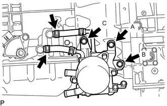
Connect the 2 oil cooler hoses to the 2 oil cooler tube unions.
-
Temporarily install the transmission oil cooler assembly with the bolt A. Install the bolt B and C tighten it to the specified torque. Then tighten the bolt A to the specified torque.
- Torque:
- 21 N*m { 214 kgf*cm, 15 ft.*lbf }
-
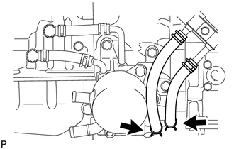
Connect the 2 oil cooler hoses to the transmission oil cooler assembly.
Note
Make sure the pinching portion of each clip are facing the directions shown in the illustration.
-
-
CONNECT WATER BY-PASS PIPE ASSEMBLY
-
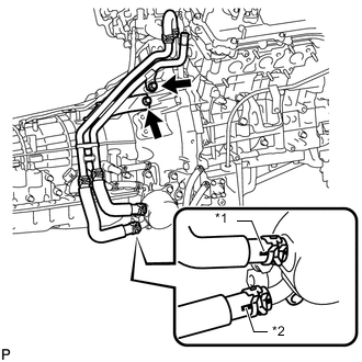
*1 White Paint Mark *2 Yellow Paint Mark Connect the 2 water by-pass hoses and install the water by-pass pipe assembly to the automatic transmission assembly with the 2 bolts.
- Torque:
- 21 N*m { 214 kgf*cm, 15 ft.*lbf }
Note
-
Make sure the pinching portion of each clip is facing the direction shown in the illustration.
-
Make sure the paint mark of each hose is facing outward.
-
-
CONNECT TRANSMISSION CONTROL CABLE ASSEMBLY
-
Connect the transmission control cable assembly to the transmission control cable bracket with a new clip, and then connect the cable end to the transmission control shaft lever LH with the nut.
- Torque:
- 14 N*m { 143 kgf*cm, 10 ft.*lbf }
-
-
INSTALL MANIFOLD STAY
-
INSTALL NO. 2 MANIFOLD STAY
-
INSTALL STARTER ASSEMBLY
-
INSTALL FRONT PROPELLER SHAFT ASSEMBLY
-
INSTALL PROPELLER SHAFT ASSEMBLY
-
CONNECT CABLE TO NEGATIVE BATTERY TERMINAL
Note
When disconnecting the cable, some systems need to be initialized after the cable is reconnected Click here.
-
ADD ENGINE COOLANT
-
ADD AUTOMATIC TRANSMISSION FLUID
-
INSPECT FOR COOLANT LEAK
-
INSPECT SHIFT LEVER POSITION
-
ADJUST SHIFT LEVER POSITION
-
INSTALL REAR ENGINE UNDER COVER ASSEMBLY
-
INSTALL NO. 1 ENGINE UNDER COVER SUB-ASSEMBLY
-
PERFORM RESET MEMORY