ВПУСКНОЙ КОЛЛЕКТОР УСТАНОВКА
Информация добавлена 08-08-2017 ![]()
PROCEDURE
-
INSTALL INTAKE MANIFOLD
-
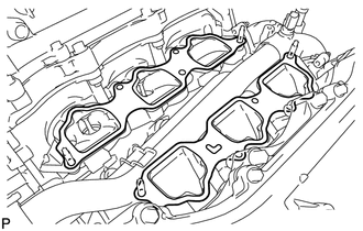
Set a new gasket on each cylinder head sub-assembly.
Note
-
Align the port holes of the gasket and cylinder head sub-assembly.
-
Be careful of the installation direction.
-
-
Set the intake manifold on the cylinder head sub-assemblies.
-
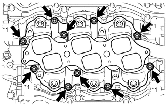
*1 Nut Install and uniformly tighten the 6 bolts and 4 nuts in several passes.
- Torque:
- 21 N*m { 214 kgf*cm, 15 ft.*lbf }
Tech Tips
Tighten the inner installation bolts of the intake manifold before tightening the outer bolts.
-
-
INSTALL FUEL DELIVERY PIPE SUB-ASSEMBLY
-
CONNECT NO. 2 FUEL PIPE SUB-ASSEMBLY
-
CONNECT NO. 1 FUEL PIPE SUB-ASSEMBLY
-
INSTALL REAR CYLINDER HEAD COVER
-
INSTALL INTAKE AIR SURGE TANK
-
Install a new gasket to the intake air surge tank.
-
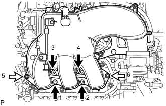

Hexagon Socket Head Cap Bolt 
Nut Using an 8 mm hexagon socket wrench, install the intake air surge tank with the 4 hexagon socket head cap bolts and 2 nuts in the order shown in the illustration.
- Torque:
- 28 N*m { 286 kgf*cm, 21 ft.*lbf }
-
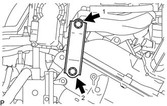
Install the throttle body bracket with the 2 bolts in the order shown in the illustration.
- Torque:
- 21 N*m { 214 kgf*cm, 15 ft.*lbf }
-
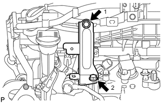
Install the No. 1 surge tank stay with the 2 bolts in the order shown in the illustration.
- Torque:
- 21 N*m { 214 kgf*cm, 15 ft.*lbf }
-
Attach the wire harness clamp to the No. 1 surge tank stay.
-
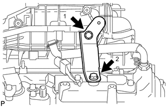
Install the No. 2 surge tank stay with the 2 bolts in the order shown in the illustration.
- Torque:
- 21 N*m { 214 kgf*cm, 15 ft.*lbf }
-
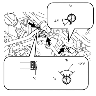
*a Front *b Top *c Matchmark Connect the No. 1 ventilation hose to the intake air surge tank, and slide the clamp to secure the hose.
-
Connect the No. 1 vacuum switching valve connector.
-
Connect the No. 1 fuel vapor feed hose to the No. 1 vacuum switching valve, and slide the clamp to secure the hose.
Tech Tips
Connect the hose so that the direction of the hose clamp is as indicated in the illustration.
-
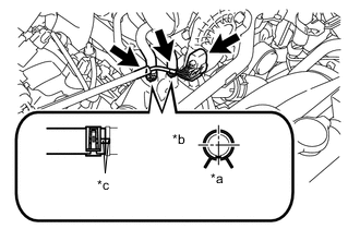
*a Front *b RH *c Matchmark Connect the throttle body connector.
-
Connect the No. 4 water by-pass hose to the water inlet housing, and slide the clamp to secure the hose.
-
Connect the No. 5 water by-pass hose to the water inlet housing, and slide the clamp to secure the hose.
Tech Tips
Connect the hose so that the direction of the hose clamp is as indicated in the illustration.
-
Attach the 2 heater hose clamps to the intake air surge tank.
-
-
INSTALL NO. 1 AIR CLEANER HOSE
-
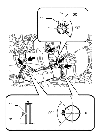
*a Top *b RH *c Front *d Paint Mark *e Protrusion *f Groove Install the No. 1 air cleaner hose with the 2 clamps.
- Torque:
- 5.0 N*m { 51 kgf*cm, 44 in.*lbf }
-
Install the bolt.
- Torque:
- 5.0 N*m { 51 kgf*cm, 44 in.*lbf }
-
Connect the vacuum hose and ventilation hose.
Tech Tips
The direction of the hose clamp is indicated in the illustration.
-
Attach the wire harness clamp.
-
-
CONNECT CABLE TO NEGATIVE BATTERY TERMINAL
Note
When disconnecting the cable, some systems need to be initialized after the cable is reconnected Click here.
-
ADD ENGINE COOLANT
-
INSPECT FOR COOLANT LEAK
-
INSPECT FOR FUEL LEAK
-
INSTALL V-BANK COVER SUB-ASSEMBLY
-
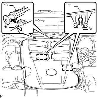
*1 V-bank Cover Sub-assembly *2 No. 1 V-bank Cover Bracket *a Pin *b Hook Attach the 2 V-bank cover sub-assembly hooks to the No. 1 V-bank cover bracket. Then align the 2 V-bank cover sub-assembly grommets with the 2 pins and press down on the V-bank cover sub-assembly to attach the pins.
-
-
INSTALL NO. 1 ENGINE UNDER COVER SUB-ASSEMBLY
-
INSTALL FRONT BUMPER COVER LOWER