ВПУСКНОЙ КОЛЛЕКТОР УСТАНОВКА
Информация добавлена 08-08-2017 ![]()
PROCEDURE
-
INSTALL INTAKE MANIFOLD
-
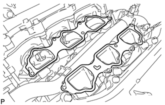
Set a new gasket on each cylinder head.
Note
-
Align the port holes of the gasket and cylinder head.
-
Be careful of the installation direction.
-
-
Set the intake manifold on the cylinder heads.
-
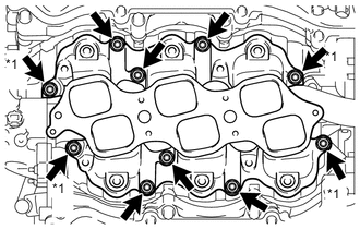
*1 Nut Install and uniformly tighten the 6 bolts and 4 nuts in several passes.
- Torque:
- 21 N*m { 214 kgf*cm, 15 ft.*lbf }
Tech Tips
Tighten the inner installation bolts of the intake manifold before tightening the outer bolts.
-
-
INSTALL FUEL DELIVERY PIPE SUB-ASSEMBLY
-
CONNECT NO.2 FUEL PIPE SUB-ASSEMBLY
-
CONNECT NO.1 FUEL PIPE SUB-ASSEMBLY
-
INSTALL REAR CYLINDER HEAD COVER
-
INSTALL INTAKE AIR SURGE TANK
-
Install a new gasket to the intake air surge tank.
-
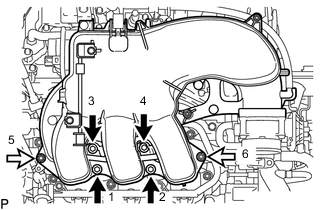

Hexagon Socket Cap Head Bolt 
Nut Using an 8 mm hexagon socket wrench, install the intake air surge tank with the 4 hexagon socket cap head bolts and 2 nuts in the order shown in the illustration.
- Torque:
- 28 N*m { 286 kgf*cm, 21 ft.*lbf }
-
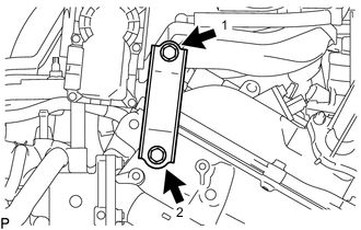
Install the throttle body bracket with the 2 bolts in the order shown in the illustration.
- Torque:
- 21 N*m { 214 kgf*cm, 15 ft.*lbf }
-
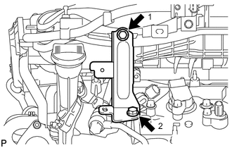
Install the No. 1 surge tank stay with the 2 bolts in the order shown in the illustration.
- Torque:
- 21 N*m { 214 kgf*cm, 15 ft.*lbf }
-
Attach the wire harness clamp.
-
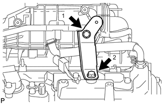
Install the No. 2 surge tank stay with the 2 bolts in the order shown in the illustration.
- Torque:
- 21 N*m { 214 kgf*cm, 15 ft.*lbf }
-
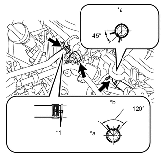
*1 Matchmark *a Front *b Top Connect the No. 1 ventilation hose.
-
Connect the No. 1 vacuum switching valve connector.
-
Connect the No. 1 fuel vapor feed hose.
Tech Tips
Connect the hose so that the direction of the hose clamp is as indicated in the illustration.
-
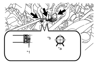
*1 Matchmark *a Front *b RH Connect the throttle body connector.
-
Connect the No. 4 water by-pass hose.
-
Connect the No. 5 water by-pass hose.
Tech Tips
Connect the hose so that the direction of the hose clamp is as indicated in the illustration.
-
Attach the 2 heater hose clamps.
-
-
INSTALL NO. 1 AIR CLEANER HOSE
-
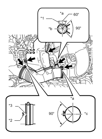
*1 Paint Mark *2 Protrusion *3 Groove *a Top *b RH *c Front Install the air cleaner hose with the 2 clamps.
- Torque:
- 5.0 N*m { 51 kgf*cm, 44 in.*lbf }
-
Install the bolt.
- Torque:
- 5.0 N*m { 51 kgf*cm, 44 in.*lbf }
-
Connect the vacuum hose and ventilation hose.
Tech Tips
The direction of the hose clamp is indicated in the illustration.
-
Attach the wire harness clamp.
-
-
CONNECT CABLE TO NEGATIVE BATTERY TERMINAL
Note
When disconnecting the cable, some systems need to be initialized after the cable is reconnected Click here.
-
ADD ENGINE COOLANT
-
INSPECT FOR COOLANT LEAK
-
INSPECT FOR FUEL LEAK
-
INSTALL V-BANK COVER SUB-ASSEMBLY
-
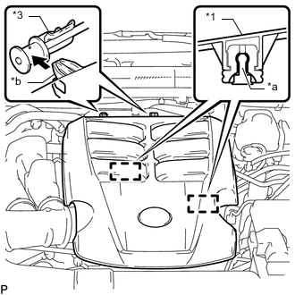
*1 V-bank Cover *2 Pin *3 Bracket *4 Hook Attach the 2 V-bank cover hooks to the bracket. Then align the 2 V-bank cover grommets with the 2 pins and press down on the V-bank cover to attach the pins.
-
-
INSTALL NO. 1 ENGINE UNDER COVER SUB-ASSEMBLY
-
INSTALL FRONT BUMPER COVER LOWER