ВПУСКНОЙ КОЛЛЕКТОР СНЯТИЕ
Информация добавлена 08-08-2017 ![]()
PROCEDURE
-
DISCHARGE FUEL SYSTEM PRESSURE
-
PRECAUTION
Note
After turning the engine switch off, waiting time may be required before disconnecting the cable from the battery terminal. Therefore, make sure to read the disconnecting the cable from the battery terminal notice before proceeding with work Click here.
-
DISCONNECT CABLE FROM NEGATIVE BATTERY TERMINAL
Note
When disconnecting the cable, some systems need to be initialized after the cable is reconnected Click here.
-
REMOVE FRONT BUMPER COVER LOWER
-
REMOVE NO. 1 ENGINE UNDER COVER SUB-ASSEMBLY
-
DRAIN ENGINE COOLANT
-
REMOVE V-BANK COVER SUB-ASSEMBLY
-
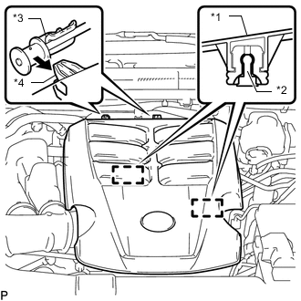
*1 V-bank Cover *2 Pin *3 Bracket *4 Hook Raise the front of the V-bank cover to detach the 2 pins. Then remove the 2 V-bank cover hooks from the bracket, and remove the V-bank cover.
-
-
REMOVE NO. 1 AIR CLEANER HOSE
-
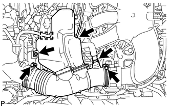
Disconnect the ventilation hose and vacuum hose.
-
Detach the wire harness clamp.
-
Remove the bolt and loosen the 2 hose clamps.
-
Remove the No. 1 air cleaner hose.
-
-
REMOVE INTAKE AIR SURGE TANK
-
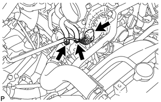
Disconnect the throttle body connector.
-
Disconnect the No. 4 water by-pass hose.
-
Disconnect the No. 5 water by-pass hose.
-
Disconnect the No. 1 fuel vapor feed hose.
-
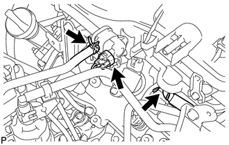
Disconnect the No. 1 vacuum switching valve connector.
-
Disconnect the No. 1 ventilation hose.
-
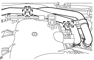
Detach the 2 heater hose clamps.
-
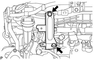
Remove the 2 bolts and throttle body bracket.
-
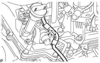
Using a clip remover, detach the wire harness clamp.
-
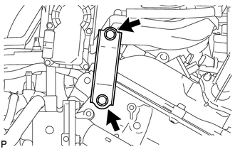
Remove the 2 bolts and No. 1 surge tank stay.
-
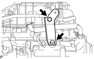
Remove the 2 bolts and No. 2 surge tank stay.
-
Using an 8 mm hexagon socket wrench, remove the 4 hexagon socket head cap bolts, 2 nuts and intake air surge tank.
-
Remove the gasket.
-
-
REMOVE REAR CYLINDER HEAD COVER
-
DISCONNECT NO.1 FUEL PIPE SUB-ASSEMBLY
-
DISCONNECT NO.2 FUEL PIPE SUB-ASSEMBLY
-
REMOVE FUEL DELIVERY PIPE SUB-ASSEMBLY
-
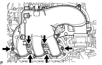
REMOVE INTAKE MANIFOLD
-
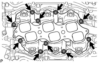
Remove the 4 nuts, 6 bolts, intake manifold and 2 gaskets.
-