ТОПЛИВНЫЙ НАСОС УСТАНОВКА

Информация добавлена 08-08-2017 ![]()
PROCEDURE
-
INSTALL FUEL SUCTION WITH PUMP AND GAUGE TUBE ASSEMBLY
-
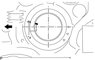
*a Co-rotation Prevention Check Mark 
Front Side of Vehicle Apply a co-rotation prevention check mark to the fuel suction with pump and gauge tube assembly.
Tech Tips
Perform this procedure when replacement of the fuel suction with pump and gauge tube assembly is necessary.
-
Apply a light coat of gasoline or grease to a new gasket and install the gasket to the fuel tank sub-assembly.
-
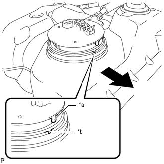
*a Protrusion *b Groove Set the fuel suction with pump and gauge tube assembly to the fuel tank sub-assembly.
Note
Be careful not to bend the arm of the fuel sender gauge assembly.
Tech Tips
Align the cutout of the fuel suction with pump and gauge tube assembly to the groove of the fuel tank sub-assembly.
-
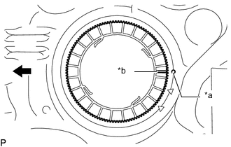
*a Rotational Start Point Mark (Fuel Tank Sub-assembly Side) *b Rotational Start Point Mark (Fuel Pump Gauge Retainer Side) Front Side of Vehicle Temporarily place the fuel pump gauge retainer by aligning the rotational start point mark of a new fuel pump gauge retainer with the rotational start point mark of the fuel tank sub-assembly while pressing the fuel suction with pump and gauge tube assembly into the fuel tank sub-assembly.
-
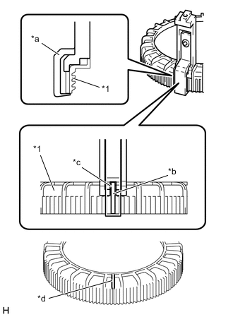
*1 Fuel Pump Gauge Retainer *a SST (Claw Set) *b Rib *c Cutout *d SST (Claw Set) Incorrect Installation Point (Rotational Start Point Mark of Fuel Pump Gauge Retainer) Set 4 SSTs (claw sets) to the fuel pump gauge retainer and temporarily install.
- SST
- 09808-14031 ( 09808-01080, 09808-01090, 09808-01100 )
Note
-
Align the cutout of SST (claw set) to the rib of the fuel pump gauge retainer.
-
Do not place SST on the rotational start point mark of the fuel pump gauge retainer, otherwise SST (claw set) cannot be set correctly.
-
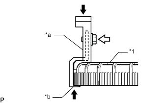
*1 Fuel Pump Gauge Retainer *a SST (Claw Set) *b Hook Press 
SST (Bolt) While firmly pressing the claw of SST (claw set) into rib of the fuel pump gauge retainer, tighten the bolt.
-
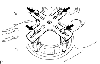
*a SST (Plate) *b SST (Claw Set) SST (Bolt) Temporarily install SST (plate) to SST (claw set) with 4 SSTs (bolts).
-
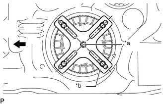
*a Center of Fuel Pump Gauge Retainer *b SST (Plate) Front Side of Vehicle Adjust the position of SST (plate) so that the setting hole of SST (handle) aligns with the center of the fuel pump gauge retainer.
-
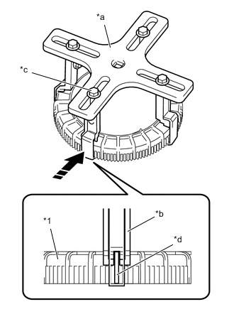
*1 Fuel Pump Gauge Retainer *a SST (Plate) *b SST (Claw Set) *c SST (Bolt) *d Rib 
Press While firmly pressing the SST (claw set) into rib of the fuel pump gauge retainer, tighten SST (bolt).
-
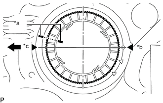
*a Co-rotation Prevention Check Mark *b Tightening Start Position *c One and Half Rotation Position Front Side of Vehicle While one person presses the fuel suction with pump and gauge tube assembly into the fuel tank sub-assembly, have another person firmly press the fuel pump gauge retainer into the threads of the fuel tank sub-assembly and tighten approximately one and a half turns.
Note
-
Do not use any tools other than SST, such as a screwdriver, etc.
-
Do not use excessive force when pressing down on SST, as the fuel suction with pump and gauge tube assembly will place excessive force on the pump gauge retainer and be difficult to remove, and parts may be damaged.
-
Do not use an impact wrench or turn the SST handle with excessive force, as parts may be damaged.
-
Do not rotate the fuel pump gauge retainer when the co-rotation prevention check mark is out of place.
-
-
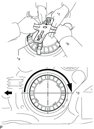
*a SST (Plate) *b Person in Charge of Tightening *c Person in Charge of Supporting *d Approximately 180° Front Side of Vehicle While one person presses the fuel suction with pump and gauge tube assembly into the fuel tank sub-assembly, have another person slowly tighten approximately 180°.
-
Check the tightening condition of the fuel pump gauge retainer.
-
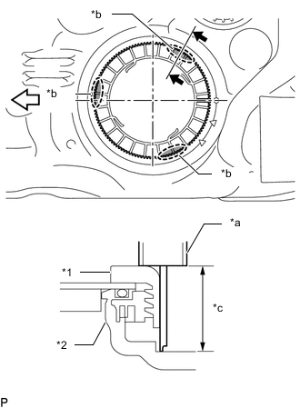
*1 Fuel Pump Gauge Retainer *2 Fuel Tank Sub-assembly *a Vernier Caliper *b Measurement Position *c Measurement Height Front Side of Vehicle Using a vernier caliper, measure the upper surface dimensions of the fuel tank sub-assembly at the 3 positions as shown in the illustration.
Standard Measurement difference is within 3 mm. Note
If the measurement difference is approximately 6 mm, the threads misaligned by 1 threads (6 mm) and the fuel pump gauge retainer must be installed again.
-
-
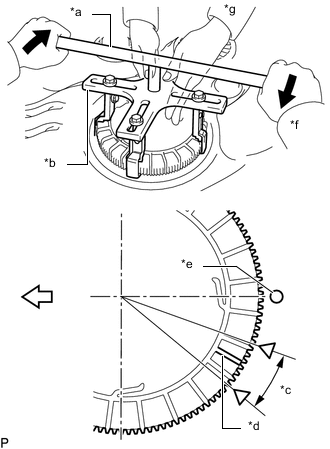
*a SST (Handle) *b SST (Plate) *c Tightening Complete Position *d Rotational Start Point Mark of Fuel Pump Gauge Retainer *e Rotational Start Point Mark of Fuel Tank Sub-assembly *f Person in Charge of Tightening *g Person in Charge of Supporting Tighten Front Side of Vehicle Install SST (handle) to SST (plate).
- SST
- 09808-14031 ( 09808-01010, 09808-01020 )
-
While one person presses the fuel suction with pump and gauge tube assembly onto the fuel tank sub-assembly, have another person use SST (handle) and slowly tighten the fuel pump gauge retainer until it reaches the tightening complete position.
-
-
INSTALL FUEL TANK MAIN TUBE SUB-ASSEMBLY AND FUEL RETURN TUBE SUB-ASSEMBLY
-
INSTALL FUEL TANK CUSHION
-
INSTALL FUEL TANK SUB-ASSEMBLY