БЛОК ЦИЛИНДРОВ РАЗБОРКА

Информация добавлена 08-08-2017 ![]()
PROCEDURE
-
INSPECT CONNECTING ROD THRUST CLEARANCE
-
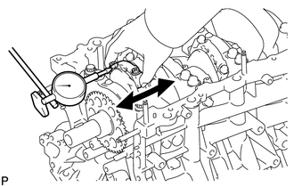
Using a dial indicator, measure the thrust clearance while moving the connecting rod back and forth.
Standard thrust clearance 0.15 to 0.30 mm (0.00591 to 0.0118 in.) Maximum thrust clearance 0.35 mm (0.0138 in.) If the thrust clearance is more than the maximum, replace one or more connecting rods as necessary.
Standard connecting rod thickness 20.80 to 20.85 mm (0.819 to 0.821 in.) If necessary, replace the crankshaft.
-
-
INSPECT CONNECTING ROD OIL CLEARANCE
-
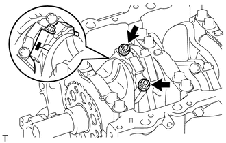
Check the matchmarks on the connecting rod and cap to ensure correct reassembly.
-
Remove the 2 connecting rod cap bolts.
-
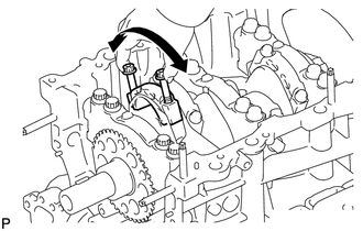
Using the 2 removed connecting rod cap bolts, remove the connecting rod cap and lower bearing by wiggling the connecting rod cap right and left.
Tech Tips
Keep the lower bearing and connecting rod cap together.
-
Clean the crank pin and bearing.
-
Check the crank pin and bearing for pitting and scratches. If the crank pin or bearing is damaged, replace the bearings. If necessary, replace the crankshaft.
-
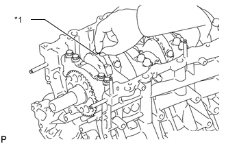
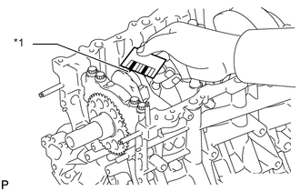
*1 Plastigage Lay a strip of Plastigage across the crank pin.
-
Install the connecting rod cap Click here.
Note
Do not turn the crankshaft.
-
Remove the 2 bolts, connecting rod cap and lower bearing.
-
*1 Plastigage 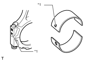
*1 Number Mark Measure the Plastigage at its widest point.
Standard oil clearance 0.040 to 0.066 mm (0.00157 to 0.00260 in.) Maximum oil clearance 0.086 mm (0.00339 in.) If the oil clearance is more than the maximum, replace the bearings. If necessary, inspect the crankshaft.
Tech Tips
If replacing a bearing, replace it with one that has the same number as the number marked on the connecting rod. There are 4 sizes of standard bearings, marked "1", "2", "3" and "4" accordingly.
Standard Connecting Rod Diameter Item Specified Condition Mark 1 59.000 to 59.006 mm (2.32283 to 2.32307 in.) Mark 2 59.007 to 59.012 mm (2.32311 to 2.32330 in.) Mark 3 59.013 to 59.018 mm (2.32334 to 2.32354 in.) Mark 4 59.019 to 59.024 mm (2.32358 to 2.32377 in.) Standard Bearing Center Wall Thickness Item Specified Condition Mark 1 1.484 to 1.487 mm (0.05843 to 0.05854 in.) Mark 2 1.487 to 1.490 mm (0.05854 to 0.05866 in.) Mark 3 1.490 to 1.493 mm (0.05866 to 0.05878 in.) Mark 4 1.493 to 1.496 mm (0.05878 to 0.05900 in.) Standard crankshaft pin diameter 55.992 to 56.000 mm (2.2044 to 2.2047 in.) -
Completely remove the Plastigage.
-
-
REMOVE PISTON SUB-ASSEMBLY WITH CONNECTING ROD
-
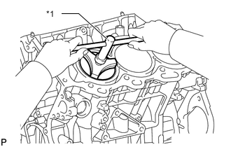
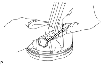
*1 Ridge Reamer Using a ridge reamer, remove all the carbon from the top of the cylinder.
-
Push out the piston with connecting rod and upper bearing through the top of the cylinder block.
Tech Tips
-
Keep the bearings, connecting rod and cap together.
-
Arrange the piston and connecting rod assemblies in the correct order.
-
-
-
REMOVE CONNECTING ROD BEARING
-
Remove the connecting rod bearings from the connecting rods and connecting rod caps.
Tech Tips
Arrange the removed parts in the correct order.
-
-
REMOVE PISTON RING SET
-
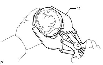
*1 Piston Ring Expander Using a piston ring expander, remove the 2 compression rings.
-
Remove the 2 side rails and oil ring (expander) by hand.
-
-
REMOVE PISTON WITH PIN SUB-ASSEMBLY
-
Disconnect the connecting rod from the piston.
-
Using a screwdriver, pry out the 2 snap rings.
-
Gradually heat the piston to approximately 80°C (176°F).
-
Using a plastic-faced hammer and brass bar, lightly tap out the piston pin and remove the connecting rod.
Tech Tips
-
The piston and pin are a matched set.
-
Arrange the pistons, pins, rings, connecting rods and bearings in the correct order.
-
-
-
-
INSPECT CRANKSHAFT THRUST CLEARANCE
-
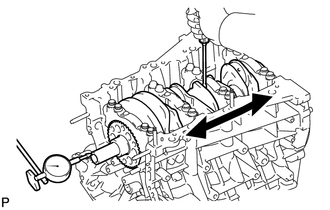
Using a dial indicator, measure the thrust clearance while prying the crankshaft back and forth with a screwdriver.
Standard thrust clearance 0.04 to 0.24 mm (0.00157 to 0.00945 in.) Maximum thrust clearance 0.30 mm (0.0118 in.) If the thrust clearance is more than the maximum, replace the thrust washers as a set.
Standard thrust washer thickness 1.93 to 1.98 mm (0.0760 to 0.0780 in.) If necessary, replace the crankshaft.
-
-
REMOVE CRANKSHAFT
-
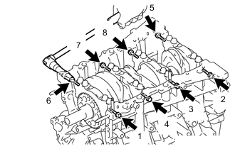
Uniformly loosen and remove the 8 bearing cap bolts and 8 seal washers in several steps in the sequence shown in the illustration.
-
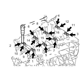
Uniformly loosen and remove the 16 bearing cap bolts in several steps in the sequence shown in the illustration.
-
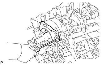
Using a screwdriver, pry out the bearing caps. Remove the 4 bearing caps.
Note
-
Push up on the cap little by little, alternating between the right and left side until the cap can be removed.
-
Be careful not to damage the joint surfaces of the cylinder block or bearing cap.
-
-
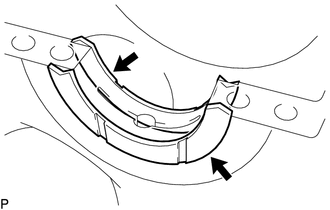
Remove the 2 lower crankshaft thrust washers.
Tech Tips
-
Keep the lower bearing and crankshaft bearing cap together.
-
Arrange the removed parts in the correct order.
-
Be sure to arrange the bearing caps and lower thrust washers in such a way that they can be reinstalled exactly as before.
-
-
Lift out the crankshaft.
-
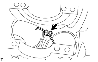
Remove the 2 upper thrust washers.
Tech Tips
-
Be sure to arrange the removed upper thrust washers in such a way that they can be reinstalled exactly as before.
-
Keep the upper bearings together with the cylinder block.
-
-
Clean each crankshaft journal and bearing.
-
Check each crankshaft journal and bearing for pitting and scratches.
If the journal or bearing is damaged, replace the bearings. If necessary, replace the crankshaft.
-
Lift out the crankshaft.
-
-
REMOVE CRANKSHAFT BEARING
-
Remove the crankshaft bearings from the bearing caps and cylinder block.
Tech Tips
Arrange the removed parts in the correct order.
-
-
REMOVE NO. 1 OIL NOZZLE SUB-ASSEMBLY
-
Using a 5 mm hexagon socket wrench, remove the 3 bolts and 3 oil nozzles.
-
-
REMOVE CONNECTING ROD SMALL END BUSH
-
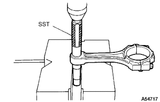
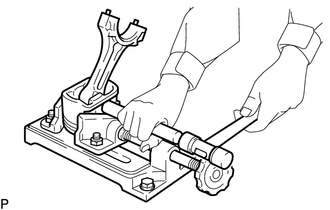
Using SST and press, press out the bush.
- SST
- 09222-30010
-
-
REMOVE STUD BOLT
Note
If a stud bolt is deformed or its threads are damaged, replace it.