ПРОКЛАДКА ГОЛОВКИ БЛОКА ЦИЛИНДРОВ СНЯТИЕ
Информация добавлена 08-08-2017 ![]()
PROCEDURE
-
REMOVE TIMING CHAIN COVER SUB-ASSEMBLY
-
SET NO. 1 CYLINDER TO TDC/COMPRESSION
-
REMOVE NO. 1 CHAIN TENSIONER ASSEMBLY
-
REMOVE CHAIN TENSIONER SLIPPER
-
REMOVE NO. 1 CHAIN SUB-ASSEMBLY
-
REMOVE NO. 1 IDLE GEAR SHAFT
-
REMOVE NO. 1 CHAIN VIBRATION DAMPER
-
REMOVE NO. 2 CHAIN VIBRATION DAMPER
-
REMOVE CRANKSHAFT TIMING SPROCKET
-
REMOVE CAMSHAFT TIMING GEARS AND NO. 2 CHAIN (for Bank 1)
-
REMOVE NO. 2 CHAIN TENSIONER ASSEMBLY
-
REMOVE CAMSHAFT BEARING CAP (for Bank 1)
-
REMOVE CAMSHAFT HOUSING SUB-ASSEMBLY RH
-
REMOVE CAMSHAFT TIMING GEARS AND NO. 2 CHAIN (for Bank 2)
-
REMOVE NO. 3 CHAIN TENSIONER ASSEMBLY
-
REMOVE CAMSHAFT BEARING CAP (for Bank 2)
-
REMOVE CAMSHAFT HOUSING SUB-ASSEMBLY LH
-
REMOVE NO. 1 VALVE ROCKER ARM SUB-ASSEMBLY
-
REMOVE VALVE LASH ADJUSTER ASSEMBLY
-
REMOVE VALVE STEM CAP
-
REMOVE REAR WATER BY-PASS JOINT
-
REMOVE CYLINDER HEAD SUB-ASSEMBLY
-
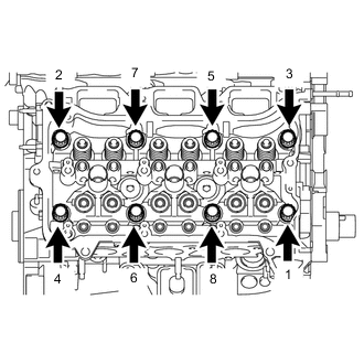
Using a 10 mm bi-hexagon wrench, uniformly loosen the 8 cylinder head bolts in the sequence shown in the illustration. Remove the 8 cylinder head bolts and plate washers.
Note
-
Be careful not to drop washers into the cylinder head sub-assembly.
-
Cylinder head warpage or cracking could result from removing bolts in an incorrect order.
Tech Tips
Arrange the removed parts in the correct order.
-
-
Remove the cylinder head sub-assembly.
-
-
REMOVE CYLINDER HEAD LH
-
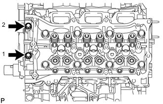
Uniformly loosen and remove the 2 cylinder head set bolts in several steps in the sequence shown in the illustration.
-
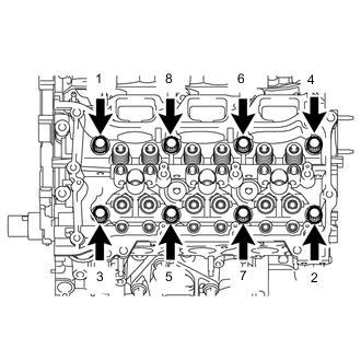
Using a 10 mm bi-hexagon wrench, uniformly loosen the 8 bolts in the sequence shown in the illustration. Remove the 8 cylinder head bolts and plate washers.
Note
-
Be careful not to drop washers into the cylinder head sub-assembly.
-
Cylinder head warpage or cracking could result from removing bolts in an incorrect order.
Tech Tips
Be sure to keep the removed parts for each installation position separate.
-
-
Remove the cylinder head LH.
-
-
REMOVE CYLINDER HEAD GASKET
-
REMOVE NO. 2 CYLINDER HEAD GASKET