Информация добавлена 08-08-2017
PROCEDURE
- Click here
INSPECT CAMSHAFT TIMING GEAR ASSEMBLY
- Click here
INSPECT CAMSHAFT TIMING EXHAUST GEAR ASSEMBLY
- Click here
INSTALL CAMSHAFT TIMING GEAR ASSEMBLY
-
Fix the camshaft in place.
Note:Be careful not to damage the camshaft.
-
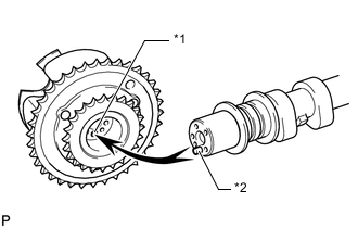
*1 Pin Hole *2 Straight Pin Put the camshaft timing gear assembly and camshaft together by aligning the pin hole and straight pin.
-
Lightly press and turn the camshaft timing gear assembly against the camshaft, and press harder after the pin enters the hole.
Note:Be sure not to turn the camshaft timing gear assembly in the retard direction.
-
Check that there is no clearance between the camshaft timing gear assembly flange and camshaft.
-
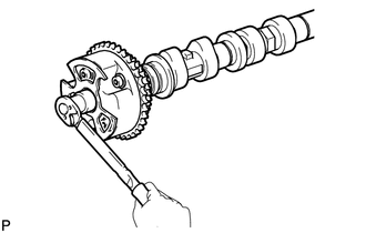
Install the flange bolt while holding the camshaft.
100 N*m 1020 kgf*cm 74 ft.*lbf -
Check the lock of the camshaft timing gear assembly.
-
Fix the camshaft in place and confirm that the camshaft timing gear assembly is locked.
Note:Be careful not to damage the camshaft.
-
-
- Click here
INSTALL CAMSHAFT TIMING EXHAUST GEAR ASSEMBLY
-
Fix the camshaft in place.
Note:Be careful not to damage the camshaft.
-
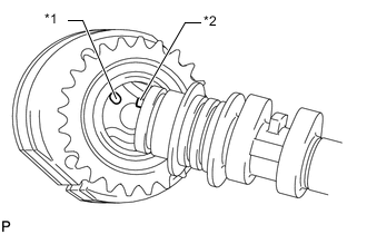
*1 Pin Hole *2 Straight Pin Put the camshaft timing exhaust gear assembly and camshaft together by aligning the pin hole and straight pin.
-
Lightly press and turn the camshaft timing gear assembly against the camshaft, and press harder after the pin enters the hole.
Note:Be sure not to turn the camshaft timing exhaust gear in the advanced direction.
-
Check that there is no clearance between the gear flange and camshaft.
-
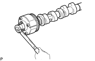
Install the flange bolt while holding the camshaft.
100 N*m 1020 kgf*cm 74 ft.*lbf -
Check the camshaft timing exhaust gear lock.
-
Make sure that the camshaft timing exhaust gear assembly locks.
-
-
- Click here
INSTALL NO. 3 CAMSHAFT
-
Check that the notch is aligned with the "0" timing mark of the timing chain cover.
-
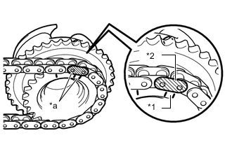
*1 Timing Mark *2 Mark Plate (yellow) *a Align Align the mark plate (yellow) with the timing mark of the camshaft timing gear as shown in the illustration and install the No. 2 chain to the camshaft timing gear.
-
Clean the camshaft housing LH and camshaft journals and apply engine oil to them.
-
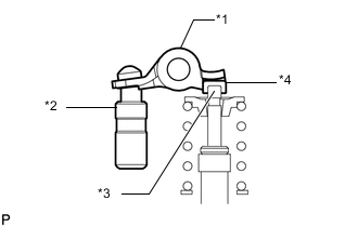
*1 Valve Rocker Arm *2 Lash Adjuster *3 Valve Stem *4 Valve Stem Cap Make sure that the No. 1 valve rocker arm sub-assembly is installed as shown in the illustration.
-
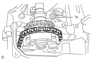
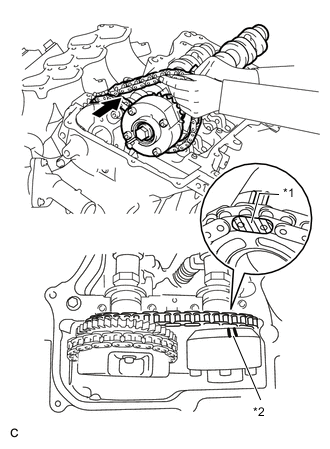
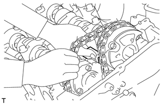
*a Place on camshaft timing gear Install the chain to the No. 3 camshaft, and then install the camshaft to the camshaft housing LH.
Tip:
-
Place the chain on the camshaft timing gear but do not engage the teeth of the sprocket and the chain.
-
Install the camshaft so that the timing mark is facing upward.
-
-
- Click here
INSTALL NO. 4 CAMSHAFT
-
Clean the camshaft housing LH and camshaft journals and apply engine oil to them.
-
*1 Mark Plate (yellow) *2 Timing Mark Pass the No. 4 camshaft through the No. 2 chain from the front of the vehicle, align the mark plate (yellow) with the timing mark and install the No. 2 chain to the camshaft timing exhaust gear.
Tip:The mark plate is yellow.
-
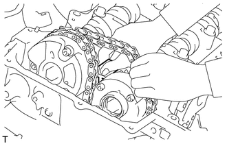
While lifting up the No. 4 camshaft, pass the No. 3 chain tensioner assembly through the No. 2 chain and set it in place.
-
Install the No. 4 camshaft to the camshaft housing LH, and then install the No. 3 chain tensioner assembly with the bolt.
21 N*m 214 kgf*cm 15 ft.*lbf
-
- Click here
INSTALL CAMSHAFT BEARING CAP (for Bank 2)
-
Clean the camshaft bearing caps and apply engine oil to them.
-

*1 Valve Rocker Arm *2 Lash Adjuster *3 Valve Stem *4 Valve Stem Cap Make sure that the No. 1 valve rocker arm sub-assembly is installed as shown in the illustration.
-
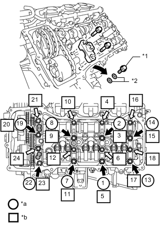
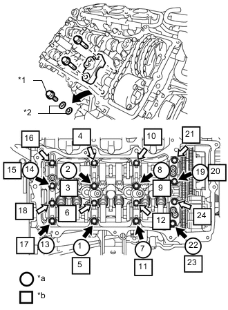
*1 Bolt *2 Washer *a Remove the bolts and washers to temporarily secure the camshaft housing *b Part to be installed 
Bolt A 
Bolt B Check the marks and numbers on the camshaft bearing caps, and then remove the replacement bolts and washers in the order shown in the illustration. Immediately after removing the bolts and washers to temporarily secure the camshaft housing in the location for a bearing cap, install the bearing cap with the bolts in the order shown in the illustration.
for bolt A 28 N*m 286 kgf*cm 21 ft.*lbf for bolt B 16 N*m 163 kgf*cm 12 ft.*lbf Note:
-
Be sure to follow the numerical order when performing this procedure.
-
Do not drop bolts and washers to temporarily secure the camshaft housing into the cylinder head.
-
-
Check the torque of each bolt again.
-
- Click here
CONNECT CHAIN SUB-ASSEMBLY (for Bank 2)
-
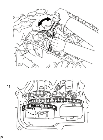
*1 Paint Mark Align the paint marks on the camshaft timing gear and No. 1 chain and install the No. 1 chain to the camshaft timing gear.
Tip:If the paint marks are not aligned, align them by turning the camshaft slightly.
-
- Click here
INSTALL CAMSHAFT
-
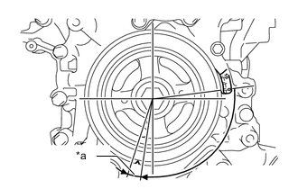
*a 5 to 10° Turn the crankshaft clockwise until it is in the position shown in the illustration so that the chain can be installed easily.
Tip:When turning the crankshaft, engine oil may spray out of the oil holes.
-
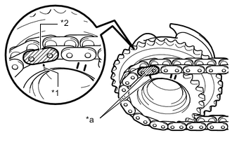
*1 Timing Mark *2 Mark Plate (yellow) *a Align Align the mark plate (yellow) with the timing mark of the camshaft timing gear as shown in the illustration and install the No. 2 chain to the camshaft timing gear.
-
Clean the camshaft housing RH and camshaft journals and apply engine oil to them.
-

*1 Valve Rocker Arm *2 Lash Adjuster *3 Valve Stem *4 Valve Stem Cap Make sure that the No. 1 valve rocker arm sub-assembly is installed as shown in the illustration.
-
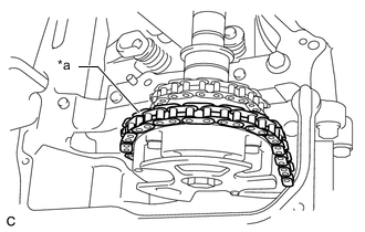
*a Place on camshaft timing gear Install the chain to the camshaft, and then install the camshaft to the camshaft housing RH.
Tip:
-
vPlace the chain on the camshaft timing gear but do not engage the teeth of the sprocket and the chain.
-
Install the camshaft so that the timing mark is facing upward.
-
-
- Click here
INSTALL NO. 2 CAMSHAFT
-
Clean the camshaft housing RH and camshaft journals and apply engine oil to them.
-
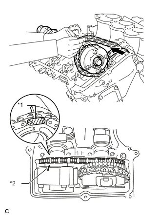
*1 Mark Plate (yellow) *2 Timing Mark Pass the No. 2 camshaft through the No. 2 chain from the front of the vehicle, align the mark plate (yellow) with the timing mark and install the No. 2 chain to the camshaft timing exhaust gear.
Tip:The mark plate is yellow.
-
While lifting up the No. 2 camshaft, pass the No. 2 chain tensioner assembly through the No. 2 chain and set it in place.
-
Install the No. 2 camshaft to the camshaft housing RH, and then install the No. 2 chain tensioner assembly with the bolt.
21 N*m 214 kgf*cm 15 ft.*lbf
-
- Click here
INSTALL CAMSHAFT BEARING CAP (for Bank 1)
-
Clean the camshaft bearing caps and apply engine oil to them.
-

*1 Valve Rocker Arm *2 Lash Adjuster *3 Valve Stem *4 Valve Stem Cap Make sure that the No. 1 valve rocker arm sub-assembly is installed as shown in the illustration.
-
*1 Bolt *2 Washer *a Remove the bolts and washers to temporarily secure the camshaft housing *b Part to be installed Bolt A Bolt B Check the marks and numbers on the camshaft bearing caps, and then remove the replacement bolts and washers in the order shown in the illustration. Immediately after removing the bolts and washers to temporarily secure the camshaft housing in the location for a bearing cap, install the bearing cap with the bolts in the order shown in the illustration.
for bolt A 28 N*m 286 kgf*cm 21 ft.*lbf for bolt B 16 N*m 163 kgf*cm 12 ft.*lbf Note:
-
Be sure to follow the numerical order when performing this procedure.
-
Do not drop bolts and washers to temporarily secure the camshaft housing into the cylinder head.
-
-
Check the torque of each bolt again.
-
- Click here
CONNECT NO. 1 CHAIN SUB-ASSEMBLY (for Bank 1)
-
*1 Paint Mark Align the paint marks on the camshaft timing gear and No. 1 chain and install the No. 1 chain to the camshaft timing gear.
Tip:If the paint marks are not aligned, align them by turning the camshaft slightly.
-
- Click here
INSTALL NO. 1 CHAIN TENSIONER ASSEMBLY
-
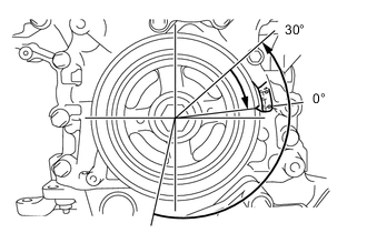
Turn the crankshaft counterclockwise 30° past the "0" timing mark, and then turn it clockwise to align the notch with the "0" timing mark.
-
Turn the crankshaft slightly to eliminate the slack in the chain.
Tip:Make sure there is some slack in the chain around the area where the chain tensioner is installed.
-
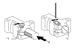
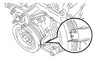
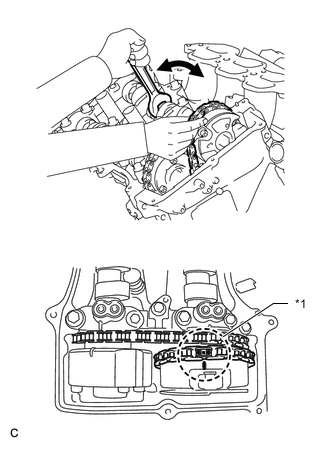
*1 Stopper Plate *a Push While turning the stopper plate of the tensioner clockwise, push in the plunger of the tensioner as shown in the illustration.
-
While turning the stopper plate of the tensioner counterclockwise, insert a pin with a diameter of 1.27 mm (0.0500 in.) into the holes in the stopper plate and tensioner to fix the stopper plate in place.
-
Install the chain tensioner with the 2 bolts.
10 N*m 102 kgf*cm 7 ft.*lbf -
Remove the pin from the No. 1 chain tensioner.
-
- Click here
INSPECT VALVE TIMING
-
Check the camshaft timing marks.
Note:
-
Check each timing mark from a viewpoint directly in line with the center of the camshaft and the timing mark on each camshaft timing gear.
-
If the timing marks are checked from any other viewpoint, the valve timing may appear misaligned.
-
-
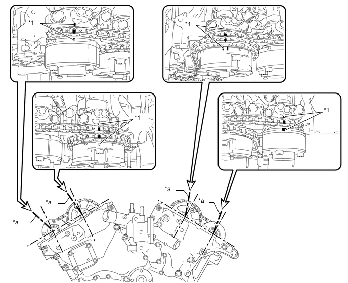
*1 Timing Mark - - *a Viewpoint - - Check that each camshaft timing mark is positioned as shown in the illustration.
Tip: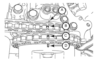
for Intake Camshaft:
Be sure to check mark A at the point when marks B, C and D are positioned in line. If the marks are checked from any other viewpoint, they cannot be checked correctly.
-
If the valve timing is misaligned, reinstall the timing chain.
-
Turn the crankshaft 2 revolutions, set the No. 1 cylinder to TDC/compression and check the timing marks again.
-
- Click here
INSTALL TIMING CHAIN COVER PLATE
-
Install a new gasket and the timing chain cover plate with the 4 bolts.
9.0 N*m 92 kgf*cm 80 in.*lbf
-
- Click here
POUR ENGINE OIL
- Click here
INSTALL CYLINDER HEAD COVER SUB-ASSEMBLY
- Click here
INSTALL CYLINDER HEAD COVER SUB-ASSEMBLY LH
- Click here
CONNECT FUEL PIPE SUB-ASSEMBLY
- Click here
INSTALL REAR CYLINDER HEAD COVER
- Click here
INSTALL NO. 2 OIL PIPE
- Click here
INSTALL NO. 1 OIL PIPE
- Click here
INSTALL WATER BY-PASS PIPE SUB-ASSEMBLY
- Click here
INSTALL ENGINE OIL LEVEL DIPSTICK GUIDE
- Click here
INSTALL GENERATOR ASSEMBLY
- Click here
INSTALL NO. 2 EXHAUST MANIFOLD HEAT INSULATOR
- Click here
INSTALL WIRING HARNESS CLAMP BRACKET
- Click here
INSTALL NO. 2 IDLER PULLEY SUB-ASSEMBLY
- Click here
CONNECT VANE PUMP ASSEMBLY
- Click here
INSTALL IGNITION COIL ASSEMBLY
- Click here
INSTALL INTAKE AIR SURGE TANK
- Click here
INSTALL FAN SHROUD
- Click here
CONNECT OIL COOLER TUBE
- Click here
INSTALL RADIATOR RESERVOIR ASSEMBLY
- Click here
INSTALL NO. 2 RADIATOR HOSE
- Click here
INSTALL NO. 1 RADIATOR HOSE
- Click here
INSTALL AIR CLEANER CASE SUB-ASSEMBLY
- Click here
INSTALL AIR CLEANER CAP AND HOSE
- Click here
INSTALL BATTERY TRAY
- Click here
INSTALL BATTERY
- Click here
CONNECT CABLE TO NEGATIVE BATTERY TERMINAL
Note:When disconnecting the cable, some systems need to be initialized after the cable is reconnected (Click here).
- Click here
ADD ENGINE OIL
- Click here
ADD ENGINE COOLANT
- Click here
CHECK ENGINE OIL LEVEL
- Click here
INSPECT FOR ENGINE OIL LEAK
- Click here
INSPECT FOR COOLANT LEAK
- Click here
INSPECT IGNITION TIMING
- Click here
INSTALL REAR ENGINE UNDER COVER ASSEMBLY
- Click here
INSTALL TRANSMISSION UNDER COVER
- Click here
INSTALL NO. 1 ENGINE UNDER COVER SUB-ASSEMBLY
- Click here
INSTALL LOWER FRONT BUMPER COVER
- Click here
INSTALL ENGINE ROOM SIDE COVER
- Click here
INSTALL ENGINE ROOM SIDE COVER LH
- Click here
INSTALL V-BANK COVER SUB-ASSEMBLY
- Click here
INSTALL UPPER RADIATOR SUPPORT SEAL