ДВИГАТЕЛЬ В СБОРЕ УСТАНОВКА

Информация добавлена 08-08-2017 ![]()
PROCEDURE
-
INSTALL ENGINE HANGER
-
REMOVE ENGINE STAND
-
Attach an engine sling device and hang the engine with a chain block.
-
Lift the engine and remove it from the engine stand.
-
Place the engine onto a work bench.
Note
-
With the exception of installing the engine assembly to an engine stand or removing the engine assembly from an engine stand, do not perform any work on the engine while it is suspended, as doing so is dangerous.
-
Pay attention to the angle of the sling device as the engine assembly or engine hangers may be damaged or deformed if the angle is incorrect.
-
-
-
INSTALL ENGINE ASSEMBLY
-
Attach an engine sling device and hang the engine with a chain block.
-
Slowly lower the engine into the engine compartment.
-
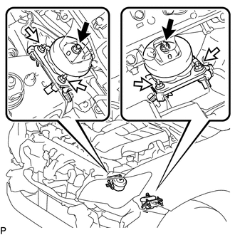

Nut A 
Nut B Install the front engine mounting insulator LH with the 3 nuts.
- Torque:
- for nut A
- 72 N*m { 734 kgf*cm, 53 ft.*lbf }
- for nut B
- 40 N*m { 408 kgf*cm, 30 ft.*lbf }
-
Install the front engine mounting insulator RH with the 3 nuts.
- Torque:
- for nut A
- 72 N*m { 734 kgf*cm, 53 ft.*lbf }
- for nut B
- 40 N*m { 408 kgf*cm, 30 ft.*lbf }
-
Remove the 4 bolts and 2 engine hangers.
-
-
INSTALL DRIVE PLATE AND RING GEAR SUB-ASSEMBLY
-
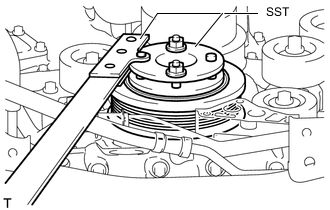
Using SST, hold the crankshaft.
- SST
- 09213-54015 ( 91651-60855 )
- 09330-00021
-
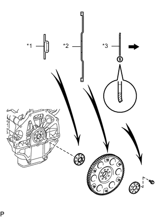
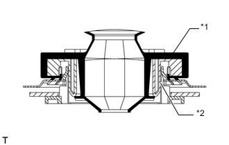
*1 Front Drive Plate Spacer *2 Drive Plate and Ring Gear *3 Rear Drive Plate Spacer Automatic Transmission Side Install the front drive plate spacer, the drive plate and ring gear, and the rear drive plate spacer to the crankshaft.
Tech Tips
As the front drive plate spacer, the drive plate and ring gear, and the rear drive plate spacer are not reversible, be sure to install them in the direction shown in the illustration.
-
Clean the bolts and bolt holes.
-
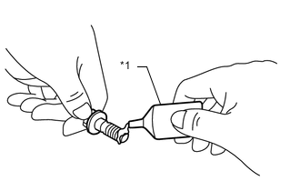
*1 Adhesive Apply a few drops of adhesive to 2 or 3 threads at the tip of each of the 8 bolts.
Adhesive Toyota Genuine Adhesive 1324, Three Bond 1324 or equivalent -
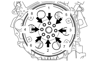
Install and uniformly tighten the 8 bolts in several steps in the sequence shown in the illustration.
- Torque:
- 83 N*m { 846 kgf*cm, 61 ft.*lbf }
Note
Do not start the engine for at least 1 hour after installing the drive plate.
-
-
INSTALL AUTOMATIC TRANSMISSION ASSEMBLY
-
INSTALL PROPELLER SHAFT ASSEMBLY
-
INSTALL FRONT PROPELLER SHAFT ASSEMBLY
-
CONNECT NO. 1 AND NO. 2 FUEL PIPES
-
Connect the No. 1 and No. 2 fuel pipes Click here.
-
Install the No. 2 fuel pipe clamp to the fuel tube connector.
-
-
CONNECT HEATER WATER HOSE ASSEMBLY
-
Connect the 4 hoses and heater water hose.
-
-
CONNECT ENGINE WIRE
-
Connect the ECM connector.
-
*1 Grommet *2 Wire Harness Support Attach the grommet to the wire harness support.
-
Pass the wire harness into the vehicle and install the wire harness support.
-
Connect the 9 connectors and attach the clamp.
-
-
Install the glove compartment door Click here.
-
Connect the connector and install the bolt.
- Torque:
- 8.0 N*m { 82 kgf*cm, 71 in.*lbf }
-
-
INSTALL DRIVE PLATE AND TORQUE CONVERTER SETTING BOLT
-
INSTALL STARTER ASSEMBLY
-
INSTALL STARTER COVER
-
INSTALL GENERATOR ASSEMBLY
-
INSTALL WIRING HARNESS CLAMP BRACKET
-
INSTALL NO. 2 IDLER PULLEY SUB-ASSEMBLY
-
INSTALL EXHAUST MANIFOLD SUB-ASSEMBLY LH
-
INSTALL NO. 2 EXHAUST MANIFOLD HEAT INSULATOR
-
INSTALL NO. 2 MANIFOLD STAY
-
INSTALL EXHAUST MANIFOLD SUB-ASSEMBLY RH
-
INSTALL NO. 1 EXHAUST MANIFOLD HEAT INSULATOR
-
INSTALL MANIFOLD STAY
-
INSTALL FRONT EXHAUST PIPE ASSEMBLY
-
INSTALL COOLER COMPRESSOR ASSEMBLY
-
CONNECT SUCTION HOSE SUB-ASSEMBLY
-
CONNECT DISCHARGE HOSE SUB-ASSEMBLY
-
CONNECT VANE PUMP ASSEMBLY
-
INSTALL FAN AND GENERATOR V BELT
-
INSTALL INTAKE AIR SURGE TANK
-
INSTALL RADIATOR ASSEMBLY
-
INSTALL FAN SHROUD
-
CONNECT OIL COOLER TUBE
-
INSTALL RADIATOR RESERVOIR ASSEMBLY
-
INSTALL NO. 2 RADIATOR HOSE
-
INSTALL NO. 1 RADIATOR HOSE
-
INSTALL RADIATOR SIDE DEFLECTOR LH
-
INSTALL RADIATOR SIDE DEFLECTOR RH
-
INSTALL AIR CLEANER CASE SUB-ASSEMBLY
-
Install the air cleaner case with the 3 bolts.
- Torque:
- 12 N*m { 122 kgf*cm, 9 ft.*lbf }
-
Attach the wire harness clamp.
-
Install the air cleaner filter element.
-
-
INSTALL AIR CLEANER CAP AND HOSE
-
INSTALL FRONT BUMPER COVER
-
INSTALL BATTERY TRAY
-
INSTALL BATTERY
-
Install the battery.
-
Install the battery hold down clamp with the 2 nuts.
- Torque:
- 6.0 N*m { 61 kgf*cm, 53 in.*lbf }
-
Connect the cable to the positive battery terminal.
-
-
INSTALL COWL TOP VENTILATOR LOUVER SUB-ASSEMBLY
-
CONNECT CABLE TO NEGATIVE BATTERY TERMINAL
Note
When disconnecting the cable, some systems need to be initialized after the cable is reconnected Click here.
-
ADD ENGINE OIL
-
ADD ENGINE COOLANT
-
INSPECT FOR ENGINE OIL LEAK
-
INSPECT FOR COOLANT LEAK
-
INSPECT FOR FUEL LEAK
-
CHECK ENGINE OIL LEVEL
-
INSPECT FOR EXHAUST GAS LEAK
-
PERFORM RESET MEMORY
-
INSPECT IGNITION TIMING
-
INSPECT ENGINE IDLE SPEED
-
INSPECT CO/HC
-
INSTALL HOOD SUB-ASSEMBLY
-
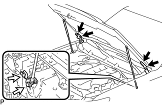
Bolt A Bolt B Install the hood with the 8 bolts.
- Torque:
- for bolt A
- 13 N*m { 133 kgf*cm, 10 ft.*lbf }
- for bolt B
- 18 N*m { 184 kgf*cm, 13 ft.*lbf }
-
Connect the washer hose.
-
-
ADJUST HOOD SUB-ASSEMBLY
-
CHARGE REFRIGERANT
-
WARM UP ENGINE
-
CHECK FOR REFRIGERANT GAS LEAK
-
INSTALL FRONT NO. 1 FENDER APRON TO FRAME SEAL RH
-
INSTALL FRONT NO. 1 FENDER APRON TO FRAME SEAL LH
-
INSTALL FRONT FENDER APRON SEAL RH
-
INSTALL FRONT FENDER APRON SEAL LH
-
INSTALL REAR ENGINE UNDER COVER ASSEMBLY
-
Install the rear engine under cover with the 4 bolts.
- Torque:
- 29 N*m { 296 kgf*cm, 21 ft.*lbf }
-
-
INSTALL TRANSMISSION UNDER COVER
-
Install the transmission under cover with the 2 bolts.
- Torque:
- 29 N*m { 296 kgf*cm, 21 ft.*lbf }
-
-
INSTALL NO. 1 ENGINE UNDER COVER SUB-ASSEMBLY
-
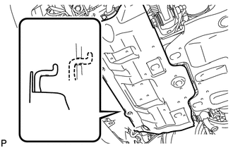
Hook the engine under cover to the vehicle body as shown in the illustration.
-
Install the 4 bolts.
- Torque:
- 29 N*m { 296 kgf*cm, 21 ft.*lbf }
-
-
INSTALL LOWER FRONT BUMPER COVER
-
Install the front bumper cover lower with the 5 bolts and clip.
- Torque:
- 8.0 N*m { 82 kgf*cm, 71 in.*lbf }
-
-
INSTALL ENGINE ROOM SIDE COVER
-
Install the engine room side cover with the 4 clips.
-
-
INSTALL ENGINE ROOM SIDE COVER LH
-
Install the engine room side cover LH with the 4 clips.
-
-
INSTALL V-BANK COVER SUB-ASSEMBLY
-
INSTALL UPPER RADIATOR SUPPORT SEAL
-
Install the upper radiator support seal with the 14 clips.
-