ДВИГАТЕЛЬ В СБОРЕ СНЯТИЕ

Информация добавлена 08-08-2017 ![]()
PROCEDURE
-
RECOVER REFRIGERANT FROM REFRIGERATION SYSTEM
-
DISCHARGE FUEL SYSTEM PRESSURE
-
PRECAUTION
Note
After turning the engine switch off, waiting time may be required before disconnecting the cable from the battery terminal. Therefore, make sure to read the disconnecting the cable from the battery terminal notice before proceeding with work Click here.
-
DISCONNECT CABLE FROM NEGATIVE BATTERY TERMINAL
Note
When disconnecting the cable, some systems need to be initialized after the cable is reconnected Click here.
-
REMOVE UPPER RADIATOR SUPPORT SEAL
-
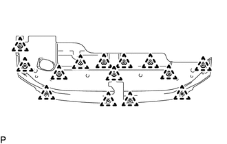
Remove the 14 clips and upper radiator support seal.
-
-
REMOVE V-BANK COVER SUB-ASSEMBLY
-
REMOVE ENGINE ROOM SIDE COVER LH
-
Remove the 4 clips and engine room side cover LH.
-
-
REMOVE ENGINE ROOM SIDE COVER
-
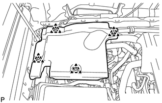
Remove the 4 clips and engine room side cover.
-
-
REMOVE HOOD SUB-ASSEMBLY
-
Disconnect the washer hose.
-
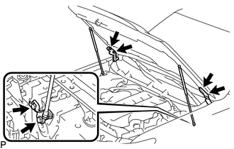
Remove the 8 bolts and hood.
Note
If the hood support is detached from the ball joint, it becomes non-reusable. Therefore, do not detach the hood support from the ball joint unless replacing it.
-
-
REMOVE COWL TOP VENTILATOR LOUVER SUB-ASSEMBLY
-
REMOVE LOWER FRONT BUMPER COVER
-
Remove the clip, 5 bolts and lower front bumper cover.
-
-
REMOVE NO. 1 ENGINE UNDER COVER SUB-ASSEMBLY
-
Remove the 4 bolts.
-
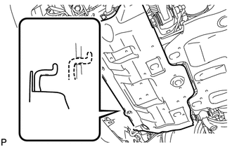
Unhook the No. 1 engine under cover from the vehicle body as shown in the illustration.
-
-
REMOVE TRANSMISSION UNDER COVER
-
Remove the 2 bolts and transmission under cover.
-
-
REMOVE REAR ENGINE UNDER COVER ASSEMBLY
-
Remove the 4 bolts and rear engine under cover.
-
-
REMOVE FRONT FENDER APRON SEAL LH
-
REMOVE FRONT FENDER APRON SEAL RH
-
REMOVE FRONT NO. 1 FENDER APRON TO FRAME SEAL LH
-
REMOVE FRONT NO. 1 FENDER APRON TO FRAME SEAL RH
-
DRAIN ENGINE OIL
-
DRAIN ENGINE COOLANT
-
REMOVE BATTERY
-
Disconnect the cable from the positive battery terminal.
-
Remove the 2 nuts and battery hold down clamp.
-
Remove the battery.
-
-
REMOVE BATTERY TRAY
-
REMOVE FRONT BUMPER COVER
-
REMOVE AIR CLEANER CAP AND HOSE
-
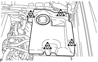
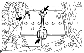
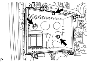
REMOVE AIR CLEANER CASE SUB-ASSEMBLY
-
Remove the air cleaner filter element.
-
Detach the wire harness clamp.
-
Remove the 3 bolts and air cleaner case.
-
-
REMOVE RADIATOR SIDE DEFLECTOR RH
-
REMOVE RADIATOR SIDE DEFLECTOR LH
-
REMOVE NO. 1 RADIATOR HOSE
-
REMOVE NO. 2 RADIATOR HOSE
-
REMOVE RADIATOR RESERVOIR ASSEMBLY
-
DISCONNECT OIL COOLER TUBE
-
REMOVE FAN SHROUD
-
REMOVE RADIATOR ASSEMBLY
-
REMOVE INTAKE AIR SURGE TANK
-
REMOVE FAN AND GENERATOR V BELT
-
DISCONNECT VANE PUMP ASSEMBLY
-
DISCONNECT DISCHARGE HOSE SUB-ASSEMBLY
-
DISCONNECT SUCTION HOSE SUB-ASSEMBLY
-
REMOVE COOLER COMPRESSOR ASSEMBLY
-
REMOVE FRONT EXHAUST PIPE ASSEMBLY
-
REMOVE MANIFOLD STAY
-
REMOVE NO. 1 EXHAUST MANIFOLD HEAT INSULATOR
-
REMOVE EXHAUST MANIFOLD SUB-ASSEMBLY RH
-
REMOVE NO. 2 MANIFOLD STAY
-
REMOVE NO. 2 EXHAUST MANIFOLD HEAT INSULATOR
-
REMOVE EXHAUST MANIFOLD SUB-ASSEMBLY LH
-
REMOVE NO. 2 IDLER PULLEY SUB-ASSEMBLY
-
REMOVE WIRING HARNESS CLAMP BRACKET
-
REMOVE GENERATOR ASSEMBLY
-
REMOVE STARTER COVER
-
REMOVE STARTER ASSEMBLY
-
REMOVE DRIVE PLATE AND TORQUE CONVERTER SETTING BOLT
-
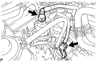
DISCONNECT ENGINE WIRE
-
Remove the bolt and disconnect the connector.
-
Remove the glove compartment door Click here.
-
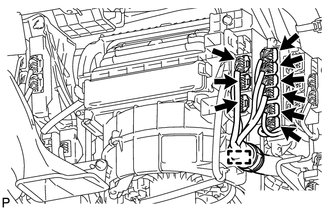
Disconnect the ECM connector.
-
Detach the clamp and disconnect the 9 connectors.
-
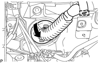
Detach the grommet from the wire harness support.
-
Detach the clamp from the wire harness bracket.
-
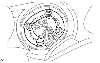
Detach the 4 claws to remove the wire harness support from the vehicle, and then pull out the ECM connector to remove it from the vehicle.
-
-
-
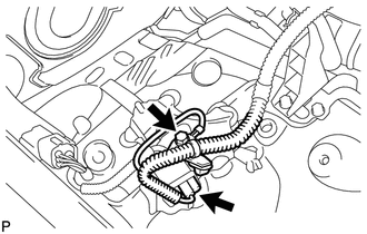
DISCONNECT HEATER WATER HOSE ASSEMBLY
-
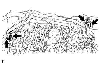
Disconnect the 4 hoses and heater water hose.
-
-
DISCONNECT NO. 1 AND NO. 2 FUEL PIPES
-
Remove the No. 2 fuel pipe clamp from the fuel tube connector.
-
Disconnect the No. 1 and No. 2 fuel pipes Click here.
-
-
REMOVE FRONT PROPELLER SHAFT ASSEMBLY
-
REMOVE PROPELLER SHAFT ASSEMBLY
-
REMOVE AUTOMATIC TRANSMISSION ASSEMBLY
-
REMOVE DRIVE PLATE AND RING GEAR SUB-ASSEMBLY
-
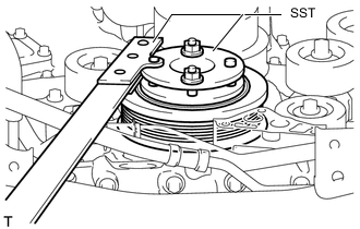
Using SST, hold the crankshaft.
- SST
- 09213-54015 ( 91651-60855 )
- 09330-00021
-
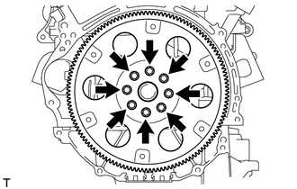
Remove the 8 bolts, the rear drive plate spacer, the drive plate and ring gear, and the front drive plate spacer.
-
-
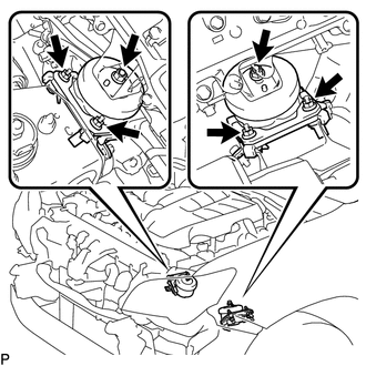
INSTALL ENGINE HANGER
-
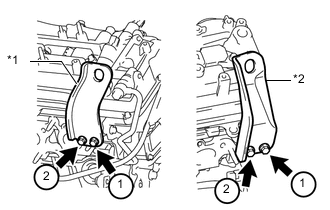
*1 No. 1 Engine Hanger *2 No. 2 Engine Hanger Install 2 engine hangers with 4 bolts as shown in the illustration.
- Torque:
- 33 N*m { 337 kgf*cm, 24 ft.*lbf }
Tech Tips
No. 1 Engine Hanger 12281-31110 No. 2 Engine Hanger 12282-31140 Bolt 91671-C0830
-
-
REMOVE ENGINE ASSEMBLY
-
Attach an engine sling device and hang the engine with a chain block.
-
Remove the 6 nuts from the front engine mounting insulator LH and RH.
-
Lift the engine out of the vehicle carefully.
Note
-
Make sure the engine is clear of all wiring and hoses.
-
With the exception of installing the engine assembly to an engine stand or removing the engine assembly from an engine stand, do not perform any work on the engine while it is suspended, as doing so is dangerous.
-
Pay attention to the angle of the sling device as the engine assembly or engine hangers may be damaged or deformed if the angle is incorrect.
-
-
Remove the front engine mounting insulator LH and RH.
-
Place the engine onto a work bench.
-
-
INSTALL ENGINE STAND
-
Install the engine to an engine stand with bolts.
-
Remove the 4 bolts and 2 engine hangers.
-