BACK DOOR DISASSEMBLY
-
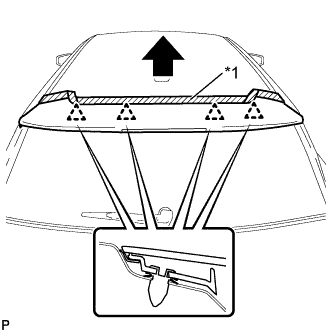
REMOVE UPPER BACK DOOR TRIM PANEL ASSEMBLY
-
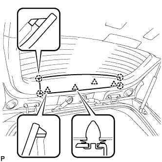
Using a moulding remover, disengage the 4 clips and 4 claws, and remove the upper back door trim panel assembly.
-
-
REMOVE BACK DOOR SIDE GARNISH LH
-
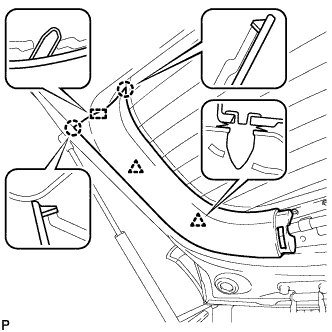
Disengage the 2 clips, 2 claws and guide, and remove the back door side garnish LH.
-
-
REMOVE BACK DOOR SIDE GARNISH RH
-
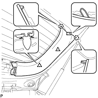
Disengage the 2 clips, 2 claws and guide, and remove the back door side garnish RH.
-
-
REMOVE BACK DOOR TRIM BOARD ASSEMBLY
-
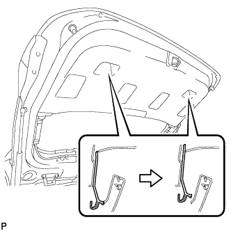
Using a screwdriver with its tip wrapped in protective tape, slide the handle plate of the back door trim board to disengage it.
-
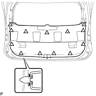
Disengage the 13 clips and remove the back door trim board assembly.
-
-
REMOVE BACK DOOR LOCK STRIKER COVER
-
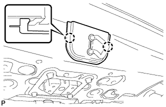
Disengage the 2 claws and remove the back door lock striker cover.
-
-
REMOVE BACK DOOR LOCK STRIKER ASSEMBLY
-
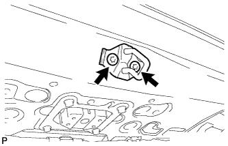
Using a T40 "TORX" socket wrench, remove the 2 screws and back door lock striker assembly.
-
-
REMOVE LOWER BACK DOOR STOPPER CUSHION
-
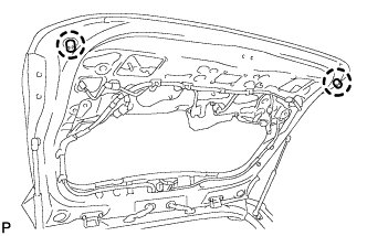
Disengage the claws to remove the 2 lower back door stopper cushions.
-
-
REMOVE BACK DOOR WEIGHT
-
Remove the 4 bolts, disengage the guide and remove the back door weight.
-
-
REMOVE REAR LIGHT ASSEMBLY LH
-

Disengage the clamp and disconnect the connector.
-
Remove the 3 nuts and rear light assembly.
-
-
REMOVE REAR LIGHT ASSEMBLY RH
Tech Tips
Use the same procedure as for the LH side.
-
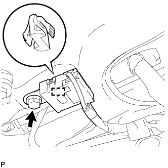
REMOVE BACK DOOR OPENER SWITCH ASSEMBLY
-
Disconnect the connector.
-
Remove the 2 bolts and back door opener switch assembly.
-
-
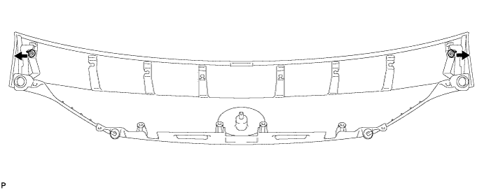
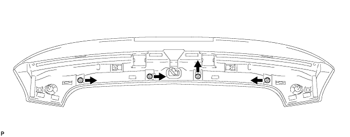
REMOVE BACK DOOR OUTSIDE GARNISH SUB-ASSEMBLY
-
Remove the 2 screws.
-
Disengage the 8 clips and remove the back door outside garnish sub-assembly.
-
Remove the 6 clips (No. 2 back door outside garnish clips) as shown in the illustration.
-
Remove the 2 clips (back door outside garnish clips) as shown in the illustration.
-
-
REMOVE LICENSE PLATE LIGHT ASSEMBLY LH
-
Disconnect the connector.
-
Disengage the 2 claws and remove the license plate light assembly.
-
-
REMOVE LICENSE PLATE LIGHT ASSEMBLY RH
Tech Tips
Use the same procedure as for the LH side.
-
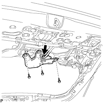
REMOVE AMPLIFIER ANTENNA ASSEMBLY
-
Disconnect the 2 connectors.
-
Remove the bolt and amplifier antenna assembly.
-
-
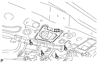
REMOVE REAR TELEVISION CAMERA ASSEMBLY (w/ Rear Monitor)
-
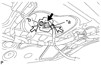
Text in Illustration *a Bolt *b Screw Disconnect the connector.
-
Remove the bolt.
-
Remove the screw and rear television camera assembly.
-
-
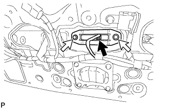
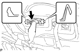
REMOVE RADIO SETTING CONDENSER
Note
When the terminal cover is removed, the radio setting condenser must be replaced because the terminal cover and condenser are supplied as a set.
-
Remove the bolt.
-
Disengage the clamp and disconnect the radio setting condenser with wire harness from the vehicle body.
-
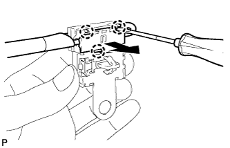
Using a screwdriver, disengage the 3 claws and remove the terminal cover with wire harness from the condenser.
-
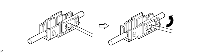
Using a screwdriver, bend back and break off the claw as shown in the illustration.
-
Remove the terminal cover from the wire harness.
-
-
REMOVE ROOF HEADLINING ASSEMBLY
-
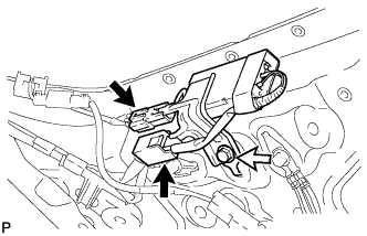
REMOVE NO. 4 ANTENNA CORD SUB-ASSEMBLY
-
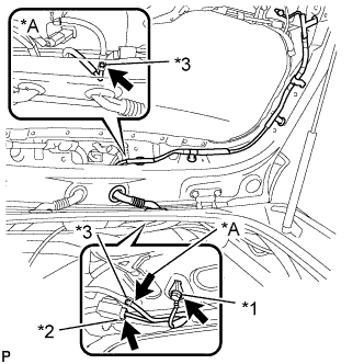
Text in Illustration *A w/ Rear Wiper *1 Bolt *2 Connector *3 Washer hose Remove the bolt.
-
Disconnect the connector.
-
w/ Rear Wiper:
-
Disconnect the washer hose.
-
-
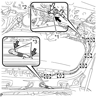
Text in Illustration *1 Connector *2 Bolt *3 Grommet Disconnect the connector.
-
Remove the bolt.
-
Disengage the 5clamps.
-
Disengage the 2 grommets and remove the No. 4 antenna cord sub-assembly.
-
-
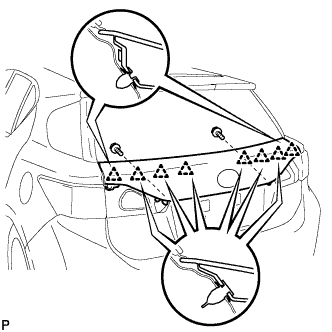
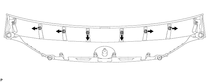
REMOVE REAR SPOILER SUB-ASSEMBLY
-
Remove the 2 hole plugs and 2 screws.
-
Remove the 2 nuts.
-
Disconnect the connector.
-
Text in Illustration *1 Protective Tape Put protective tape around the rear spoiler sub-assembly.
-
Disengage the 4 clips and remove the rear spoiler sub-assembly.
-
Remove the 4 clips as shown in the illustration.
-
-
REMOVE REAR WASHER NOZZLE (w/ Rear Wiper)
-
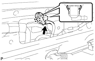
Disconnect the washer hose.
-
Disengage the 2 claws and remove the rear washer nozzle.
-
-
REMOVE REAR WIPER ARM HEAD CAP (w/ Rear Wiper)
-
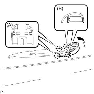
Disengage the 2 claws (A) and open the rear wiper arm head cap as shown in the illustration.
-
Disengage the 2 claws (B) and remove the rear wiper arm head cap.
-
-
REMOVE REAR WIPER ARM AND BLADE ASSEMBLY (w/ Rear Wiper)
-
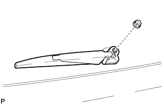
Remove the nut and the rear wiper arm and blade assembly.
-
-
REMOVE REAR WIPER MOTOR GROMMET (w/ Rear Wiper)
-
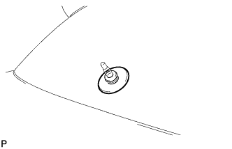
Remove the rear wiper motor grommet.
-
-
REMOVE REAR WIPER MOTOR ASSEMBLY (w/ Rear Wiper)
-
Disconnect the connector.
-
Remove the 3 bolts and the rear wiper motor assembly.
-
-
REMOVE BACK DOOR STAY ASSEMBLY LH
Note
-
Avoid touching the piston rod as much as possible to prevent foreign matter from attaching to it. Be sure to hold the cylinder while servicing.
-
Do not wear cotton gloves or other similar materials when handling the piston rod. Fibers may attach to the rod and result in gas leaks.
-
Do not apply any horizontal load to the door stay in order to prevent the piston rod from deforming.
-
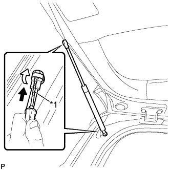
Text in Illustration *1 Protective Tape Using a screwdriver, remove the stop ring along the groove.
Tech Tips
Tape the screwdriver tip before use.
-
Release the ball joint and remove the back door stay assembly.
Note
Remove the back door stay assembly while supporting the back door by hand.
-
-
REMOVE BACK DOOR STAY ASSEMBLY RH
Tech Tips
Use the same procedure as for the LH side.
-
REMOVE BACK DOOR STAY BOLT LH
-
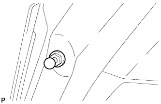
Remove the back door stay bolt.
-
-
REMOVE BACK DOOR STAY BOLT RH
Tech Tips
Use the same procedure as for the LH side.