FRONT DOOR DISASSEMBLY
-
PRECAUTION
Note
After turning the power switch off, waiting time may be required before disconnecting the cable from the negative (-) battery terminal. Therefore, make sure to read the disconnecting the cable from the negative (-) battery terminal notices before proceeding with work Click here.
-
REMOVE REAR NO. 2 FLOOR BOARD
-
Remove the rear No. 2 floor board.
-
-
REMOVE REAR DECK FLOOR BOX
-
Remove the rear deck floor box.
-
-
REMOVE REAR NO. 3 FLOOR BOARD
-
Remove the rear No. 3 floor board.
-
-
REMOVE DECK FLOOR BOX RH
-
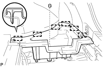
Remove the clip.
-
Disengage the 6 guides and remove the deck floor box RH.
-
-
REMOVE REAR FLOOR BOARD UPPER NO. 3 PLATE
-
Disengage the 4 claws and 2 guides, and remove the rear floor board upper No. 3 plate.
-
-
DISCONNECT CABLE FROM NEGATIVE BATTERY TERMINAL
Note
When disconnecting the cable, some systems need to be initialized after the cable is reconnected Click here.
-
REMOVE FRONT DOOR INSIDE HANDLE BEZEL PLUG
-
Using a moulding remover, disengage the 3 claws and remove the front door inside handle bezel plug as shown in the illustration.
-
-
REMOVE FRONT DOOR LOWER FRAME BRACKET GARNISH
-
Disengage the clip and claw, and remove the front door lower frame bracket garnish.
-
-
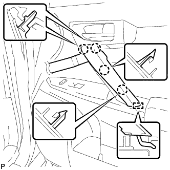
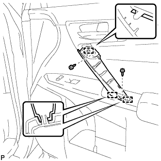
REMOVE POWER WINDOW REGULATOR MASTER SWITCH ASSEMBLY WITH FRONT DOOR ARMREST BASE PANEL (for Driver Side)
-
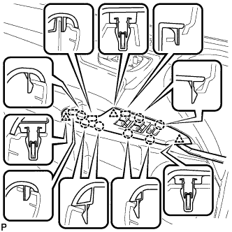
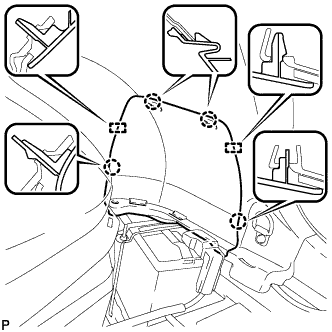
Using a moulding remover, disengage the 3 clips, 7 claws and 2 guides as shown in the illustration.
-
Disconnect the connector and remove the power window regulator master switch assembly with front door armrest base panel.
-
-
REMOVE DOOR ARMREST COVER (for Driver Side)
-
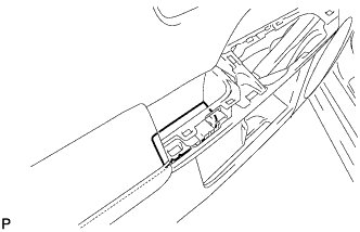
Remove the door armrest cover.
-
-
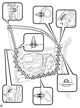
REMOVE FRONT DOOR TRIM BOARD SUB-ASSEMBLY (for Driver Side)
-
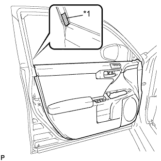
Text in Illustration *1 Protective Tape Put protective tape around the front door panel.
-
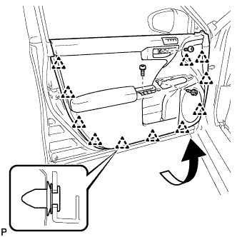
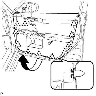
Remove the 3 screws.
-
Using a clip remover, disengage the 11 clips.
-
Pull out the front door trim board sub-assembly in the direction indicated by the arrow in the illustration.
-
Raise the front door trim board sub-assembly and remove it.
-
w/ Seat Position Memory System:
-
Disconnect the connector.
-
-
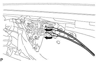
Disconnect the front door lock remote control cable assembly and front door inside locking cable assembly.
-
-
REMOVE DOOR ASSIST GRIP COVER (for Front Passenger Side)
-
for Type A:
-
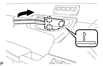
Using a moulding remover, disengage the 4 claws and guide to remove the door assist grip cover.
-
-
for Type B:
-
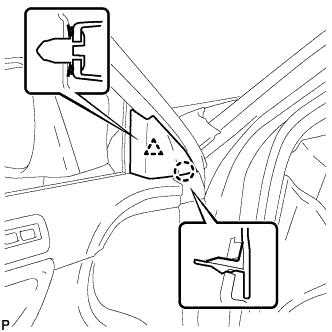
Using a moulding remover, disengage the 2 clips, 2 claws and guide to remove the door assist grip cover.
-
Remove the 2 clips from the door assist grip assembly.
-
-
-
REMOVE DOOR ASSIST GRIP ASSEMBLY (for Front Passenger Side)
-
Remove the 2 screws.
-
Disengage the 3 guides and remove the door assist grip assembly.
-
-
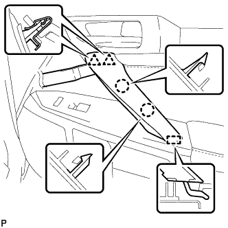
REMOVE POWER WINDOW REGULATOR SWITCH ASSEMBLY WITH FRONT DOOR ARMREST BASE PANEL (for Front Passenger Side)
-
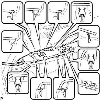
Using a moulding remover, disengage the 3 clips, 8 claws and 4 guides as shown in the illustration.
-
Disconnect each connector and remove the power window regulator switch assembly with front door armrest base panel.
-
-
REMOVE FRONT DOOR TRIM BOARD SUB-ASSEMBLY (for Front Passenger Side)
-
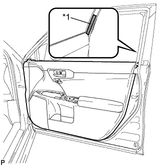
Text in Illustration *1 Protective Tape Put protective tape around the front door panel.
-
Remove the 2 screws.
-
Using a clip remover, disengage the 11 clips.
-
Pull out the front door trim board sub-assembly in the direction indicated by the arrow in the illustration.
-
Raise the front door trim board sub-assembly and remove the front door trim board sub-assembly .
-
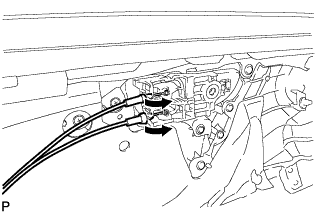
Disconnect the front door lock remote control cable assembly and front door inside locking cable assembly.
-
-
REMOVE FRONT DOOR INSIDE HANDLE SUB-ASSEMBLY
-
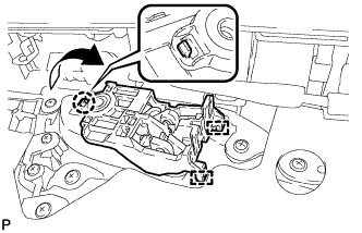
Disengage the claw and 2 guides, and remove the front door inside handle sub-assembly as shown in the illustration.
-
-
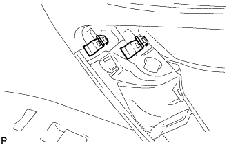
REMOVE SEAT MEMORY SWITCH (w/ Seat Position Memory System)
-
Disconnect the connector.
-
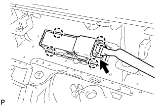
Disengage the 4 claws and remove the seat memory switch.
-
-
REMOVE FRONT DOOR WIRING SUB-ASSEMBLY (w/ Seat Position Memory System)
-
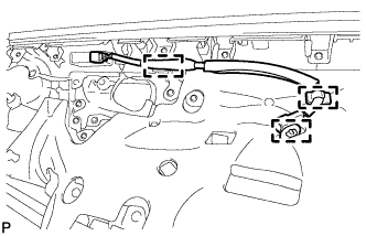
Disengage the 3 clamps and remove the front door wiring sub-assembly.
-
-
REMOVE FRONT DOOR INNER GLASS WEATHERSTRIP
-
Disengage the 8 claws and remove the front door inner glass weatherstrip as shown in the illustration.
-
-
REMOVE FRONT DOOR TRIM SEAL
-
Using a clip remover, disengage the 8 clips and remove the front door trim seal.
-
-
REMOVE DOOR FRAME GARNISH
-
Disengage the clip and remove the door frame garnish.
Tech Tips
This garnish needs to be replaced with a new one because the clip will break when removing it.
-
-
REMOVE FRONT NO. 1 SPEAKER ASSEMBLY
-
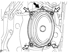
Disconnect the connector.
-
Remove the 4 bolts and front No. 1 speaker assembly.
Note
Do not touch the speaker cone.
-
-
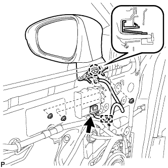
REMOVE OUTER MIRROR CONTROL ECU ASSEMBLY (w/ Memory)
-
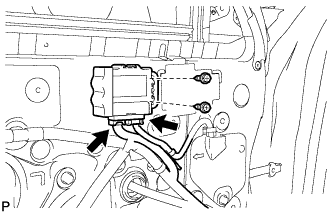
Disconnect each connector.
-
Remove the 2 screws and outer mirror control ECU assembly.
-
-
REMOVE OUTER MIRROR INSTALL HOLE COVER
-
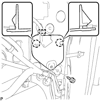
Remove the screw.
-
Disengage the 2 claws.
-
Disengage the clamp and remove the outer mirror install hole cover.
-
-
REMOVE OUTER MIRROR PROTECTOR
-
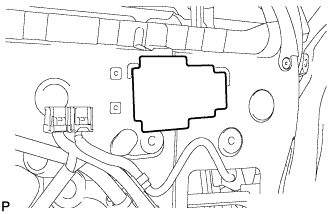
Remove the outer mirror protector.
Tech Tips
Remove any remaining adhesive residue on the door.
-
-
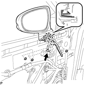
REMOVE OUTER REAR VIEW MIRROR ASSEMBLY
-
w/o Memory:
-
Disconnect the connector.
-
Disengage the clamp.
-
Remove the 3 nuts.
-
-
w/ Memory:
-
Disconnect the connector.
-
Disengage the clamp.
-
Remove the 3 nuts.
-
-
Disengage the claw and remove the outer rear view mirror assembly.
-
-
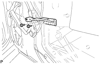
REMOVE WIRING HARNESS CLAMP BRACKET (w/o Memory)
-
Disengage the clamp.
-
Remove the 2 screws and wiring harness clamp bracket.
-
-
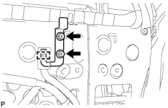
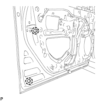
REMOVE FRONT DOOR TRIM BRACKET (for Driver Side)
-
Remove the 2 screws and front door trim bracket.
-
-
REMOVE FRONT DOOR TRIM BRACKET (for Front Passenger Side)
-
Remove the 2 screws and front door trim bracket.
-
-
REMOVE FRONT DOOR SERVICE HOLE COVER
-
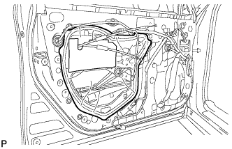
Remove the front door service hole cover.
Tech Tips
Remove any remaining butyl tape from the door.
-
-
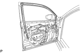
REMOVE FRONT DOOR GLASS SUB-ASSEMBLY
-
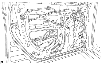
Remove the grommet.
-
Connect the cable to the negative (-) battery terminal.
-
Connect the power window regulator master switch assembly and move the front door glass sub-assembly so that the door glass bolts can be seen.
-
Disconnect the cable from the negative (-) battery terminal.
Note
When disconnecting the cable, some systems need to be initialized after the cable is reconnected Click here.
-
Disconnect the power window regulator master switch assembly.
-
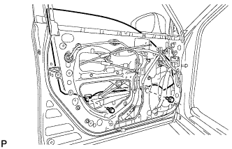
Remove the 2 bolts.
Note
After the bolts are removed, do not allow the door glass to fall.
-
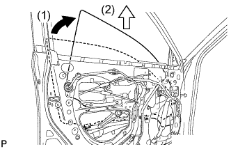
Remove the front door glass sub-assembly as indicated by the arrows, in the order shown in the illustration.
Note
Do not damage the door glass.
-
-
REMOVE FRONT DOOR WINDOW REGULATOR ASSEMBLY
-
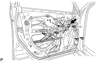
Text in Illustration *1 Temporary Bolt Disconnect the connector.
-
Loosen the temporary bolt.
Note
Do not remove the temporary bolt. If the temporary bolt is removed, the front door window regulator may fall and cause damage.
-
Remove the 5 bolts.
-
Remove the front door window regulator assembly.
-
Remove the temporary bolt from the front door window regulator assembly.
-
-
REMOVE FRONT POWER WINDOW REGULATOR MOTOR ASSEMBLY
-
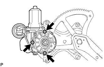
Using a T25 "TORX" socket wrench, remove the 3 screws and front power window regulator motor assembly.
-
-
REMOVE FRONT DOOR GLASS RUN
-
Remove the front door glass run.
-
-
REMOVE NO. 2 FRONT DOOR STIFFENER CUSHION
-
Text in Illustration *1 Double-sided Tape Remove the 2 bolts.
-
Disengage the 2 guides and remove the No. 2 front door stiffener cushion.
-
-
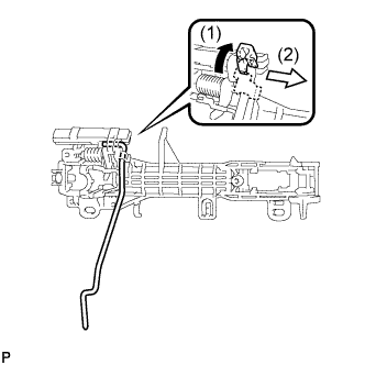
REMOVE FRONT DOOR REAR LOWER FRAME SUB-ASSEMBLY
-
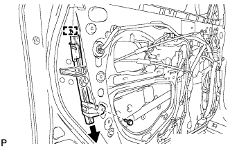
Remove the bolt.
-
Disengage the guide and remove the bolt and front door rear lower frame sub-assembly as shown in the illustration.
-
-
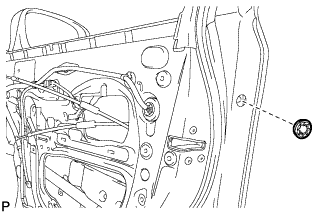
REMOVE FRONT DOOR OUTSIDE HANDLE COVER WITH LOCK CYLINDER ASSEMBLY (for Driver Side)
-
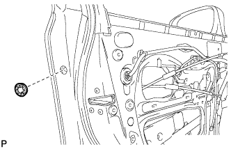
Remove the hole plug.
-
Using a T30 "TORX" socket wrench, loosen the screw and remove the front door outside handle cover with lock cylinder assembly.
Tech Tips
The screw cannot be removed because it is integrated into the front door outside handle frame sub-assembly.
-
-
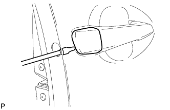
REMOVE FRONT DOOR OUTSIDE HANDLE COVER (for Driver Side)
-
Using a screwdriver, disengage the claw and 2 guides, and remove the front door outside handle cover as shown in the illustration.
-
-
REMOVE FRONT DOOR OUTSIDE HANDLE COVER (for Front Passenger Side)
-
Remove the hole plug.
-
Using a T30 "TORX" socket wrench, loosen the screw and remove the front door outside handle cover.
Tech Tips
The screw cannot be removed because it is integrated into the front door outside handle frame sub-assembly.
-
-
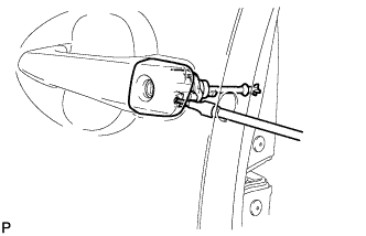
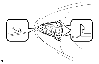
REMOVE FRONT DOOR OUTSIDE HANDLE ASSEMBLY
-

Disengage the 2 claws.
-
Disconnect the connector.
-
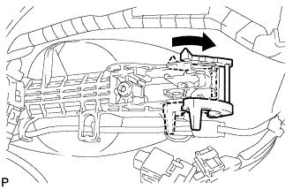
Move the lever in the direction indicated by the arrow in the illustration.
-
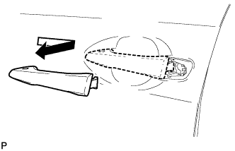
Remove the front door outside handle assembly as shown in the illustration.
-
-
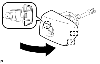
REMOVE FRONT DOOR FRONT OUTSIDE HANDLE PAD
-
Disengage the 3 claws and remove the front door front outside handle pad.
-
-
REMOVE FRONT DOOR REAR OUTSIDE HANDLE PAD
-
Disengage the 2 claws and remove the front door rear outside handle pad.
-
-
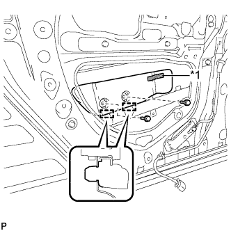
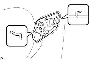
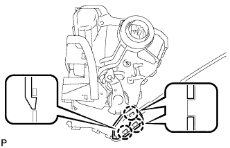
REMOVE FRONT DOOR LOCK ASSEMBLY
-

Disconnect the connector.
-
Using a T30 "TORX" socket wrench, remove the 3 screws.
-
Slide the front door lock assembly downward, and remove the front door lock assembly and cables as a unit.
-
Remove the door lock wiring harness seal from the front door lock assembly.
-
-
REMOVE FRONT DOOR LOCK REMOTE CONTROL CABLE ASSEMBLY
-
Remove the front door lock remote control cable assembly.
-
-
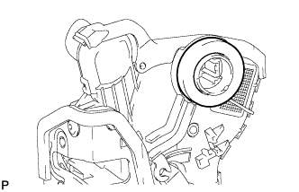
REMOVE FRONT DOOR INSIDE LOCKING CABLE ASSEMBLY
-
Using a screwdriver, disengage the 3 claws.
Tech Tips
Tape the screwdriver tip before use.
-
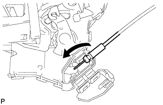
Remove the front door inside locking cable assembly.
-
-
REMOVE FRONT DOOR WIRE
-
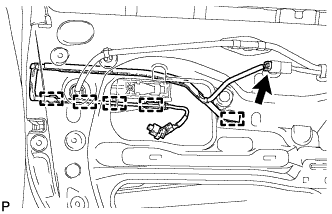
Disconnect the connector.
-
Disengage the 5 clamps and remove the front door wire.
-
-
REMOVE FRONT DOOR OUTSIDE HANDLE FRAME SUB-ASSEMBLY
-
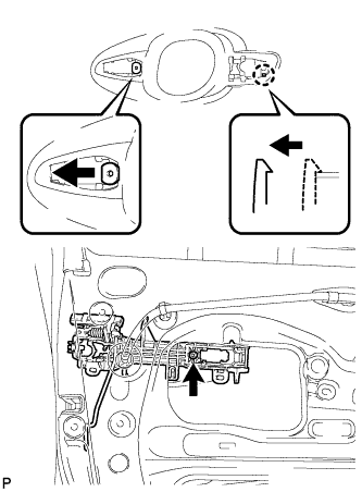
Using a T30 "TORX" socket wrench, loosen the screw.
-
Slide the front door outside handle frame sub-assembly to disengage the door handle nut and claw of the front door outside handle frame sub-assembly, and then remove it.
-
-
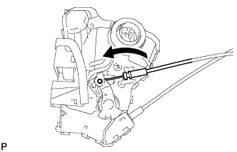
REMOVE FRONT DOOR LOCK OPEN ROD
-
Remove the front door lock open rod as indicated by the arrows, in the order shown in the illustration.
-
-
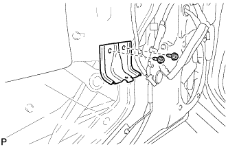
REMOVE FRONT DOOR CHECK ASSEMBLY
-
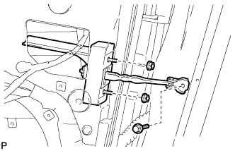
Remove the bolt, 2 nuts and front door check assembly.
-
-
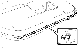
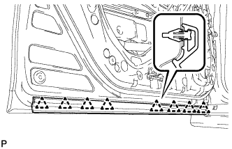
REMOVE FRONT DOOR WEATHERSTRIP
-
Text in Illustration *1 Double-sided Tape Using a clip remover, disengage the 20 clips and remove the front door weatherstrip.
-
-
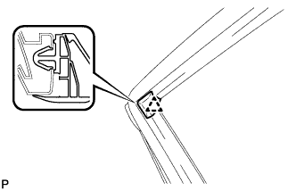
REMOVE FRONT DOOR NO. 2 WEATHERSTRIP
-
Using a clip remover, disengage the 8 clips and remove the front door No. 2 weatherstrip.
-
-
REMOVE FRONT DOOR PANEL CUSHION
-
Using a clip remover, disengage the 2 claws and remove the 2 front door panel cushions.
-
-
REMOVE DOOR DUST PROOF SEAL
-
Remove the door dust proof seal.
-
-
REMOVE FRONT DOOR FRONT LOWER FRAME UPPER COVER
-
Text in Illustration *1 Double-sided Tape Disengage the 2 clips and remove the front door front lower frame upper cover.
-
-
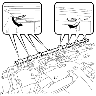
REMOVE FRONT DOOR BELT MOULDING ASSEMBLY
-
Text in Illustration *1 Protective Tape Put protective tape around the front door belt moulding assembly.
-
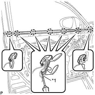
Text in Illustration *1 Protective Tape Using a screwdriver with the tip wrapped with protective tape, disengage the 7 claws and remove the front door belt moulding assembly.
-
-
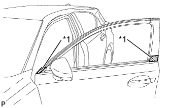
REMOVE FRONT DOOR OUTSIDE STRIPE
-
Using a heat light, heat the front door outside stripe and vehicle body.
Heating Temperature Item Temperature Vehicle Body and Front Door Outside Stripe 40 to 60°C (104 to 140°F) Note
Do not heat the vehicle body excessively.
-
Pull back on one of the ends of the front door outside stripe to remove it.
Tech Tips
When pulling on the stripe, pull it parallel to the body.
-
-
REMOVE FRONT DOOR REAR OUTSIDE STRIPE
-
Using a heat light, heat the front door rear outside stripe and vehicle body.
Heating Temperature Item Temperature Vehicle Body and Front Door Rear Outside Stripe 40 to 60°C (104 to 140°F) Note
Do not heat the vehicle body excessively.
-
Pull back on one of the ends of the front door rear outside stripe to remove it.
Tech Tips
When pulling on the stripe, pull it parallel to the body.
-
-
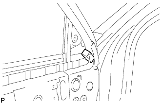
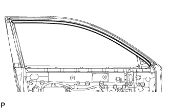
REMOVE FRONT DOOR REAR WINDOW FRAME MOULDING
Tech Tips
When removing the front door rear window frame moulding, heat the vehicle body and front door rear window frame moulding using a heat light.
Heating Temperature Item Temperature Vehicle Body 40 to 60°C (104 to 140°F) Moulding 20 to 30°C (68 to 86°F) Note
Do not heat the vehicle body or moulding excessively.
-
Using a heat light, heat the front door rear window frame moulding.
-
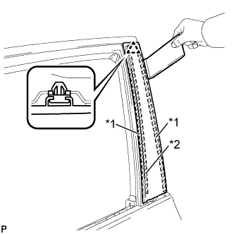
Text in Illustration *1 Double-sided Tape *2 Caulking Sponge Using a moulding remover, disengage the clip and remove the front door rear window frame moulding.
-
-
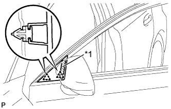
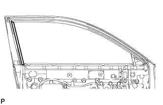
REMOVE FRONT DOOR UPPER WINDOW FRAME MOULDING
-
Insert a 4.0 mm (0.157 in.) drill bit into a drill.
-
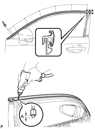
Tape a 4.0 mm (0.157 in.) drill bit 5.0 mm (0.197 in.) from the tip as shown in the illustration.
Area Dimension A 5.0 mm Note
Tape the 4.0 mm (0.157 in.) drill bit to prevent the drill bit from going too deep.
-
Lightly press the drill against the rivets to drill off the rivet flanges, and remove the 8 rivets.
Note
-
Pressing the drill too firmly will cause the rivet to turn and result in the rivet not being drilled through.
-
Prying the rivets with the drill may damage the rivet installation holes or drill bit.
-
Be careful of the drilled rivets, as they may be hot.
-
-
Using a vacuum cleaner, remove the rivet fragments and shavings from the drilled areas.
-
Disengage the guide and remove the front door upper window frame moulding from the door frame.
-