HOOD LOCK CONTROL CABLE ASSEMBLY INSTALLATION
-
INSTALL HOOD LOCK CONTROL CABLE ASSEMBLY (for LHD)
-
Pass the hood lock control cable assembly into the engine compartment.
-
Pass the cable through the upper radiator support.
-
Engage each clamp.
-
-
INSTALL HOOD LOCK CONTROL CABLE ASSEMBLY (for RHD)
-
Pass the hood lock control cable assembly into the engine compartment.
-
Pass the cable through the upper radiator support.
-
Engage each clamp.
-
-
INSTALL HOOD LOCK ASSEMBLY (w/o Engine Hood Courtesy Switch)
-
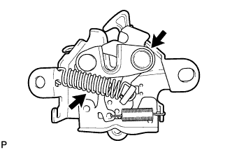
Apply MP grease to the sliding areas of the lock.
-
Connect the hood lock control cable.
-
Install the hood lock assembly with the 2 bolts and hood lock bolt.
- Torque:
- 8.0 N*m { 82 kgf*cm, 71 in.*lbf }
-
Install a new hood lock nut cap.
-
-
INSTALL HOOD LOCK ASSEMBLY (w/ Engine Hood Courtesy Switch)
-
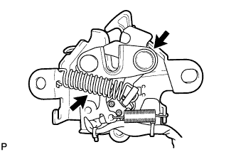
Apply MP grease to the sliding areas of the lock.
-
Connect the hood lock control cable.
-
Install the hood lock assembly with the 2 bolts and hood lock bolt.
- Torque:
- 8.0 N*m { 82 kgf*cm, 71 in.*lbf }
-
Install a new hood lock nut cap.
-
Engage the clamp.
-
Connect the connector.
-
-
INSTALL HOOD LOCK CONTROL LEVER SUB-ASSEMBLY
-
Connect the hood lock control cable assembly and install the hood lock control lever sub-assembly.
-
-
CONNECT HOOD LOCK CONTROL LEVER SUB-ASSEMBLY
-
Engage the 2 guides and claw to connect the hood lock control lever sub-assembly.
-
-
INSTALL NO. 1 INSTRUMENT PANEL UNDER COVER SUB-ASSEMBLY (for LHD)
-
Connect each connector.
-
Engage the clamp.
-
Engage the clip.
-
Install the No. 1 instrument panel under cover sub-assembly with the 2 screws <E>.
-
-
INSTALL COWL SIDE TRIM SUB-ASSEMBLY LH (for LHD)
-
Engage the claw and clip.
Note
-
Be sure to engage the clip securely.
-
If there is any damage, replace the garnish clip with a new one.
-
-
Install the cowl side trim sub-assembly LH with the clip.
-
-
INSTALL FRONT DOOR SCUFF PLATE LH (for LHD)
-
Engage the 4 claws, 2 guides and 4 clips to install the front door scuff plate LH.
-
-
INSTALL NO. 1 INSTRUMENT PANEL UNDER COVER SUB-ASSEMBLY (for RHD)
-
Connect each connector.
-
Engage the clamp.
-
Engage the 2 clips.
-
Install the No. 1 instrument panel under cover sub-assembly with the screw <E>.
-
-
INSTALL COWL SIDE TRIM SUB-ASSEMBLY RH (for RHD)
Tech Tips
Use the same procedure for the RH side and LH side Click here.
-
INSTALL FRONT DOOR SCUFF PLATE RH (for RHD)
Tech Tips
Use the same procedure for the RH side and LH side Click here.
-
INSTALL FRONT FENDER LINER LH (for LHD)
Tech Tips
Use the same procedure for the RH side and LH side Click here.
-
INSTALL FRONT WHEEL LH (for LHD)
- Torque:
- 103 N*m { 1050 kgf*cm, 76 ft.*lbf }
-
INSTALL FRONT FENDER LINER RH (for RHD)
-
Install the front fender liner RH with the 6 clips and 6 screws.
-
Install the bolt.
-
Install 2 new grommets.
-
Using a 4 mm hexagon wrench, install the 3 screws.
-
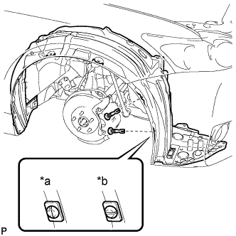
Text in Illustration *a Correct *b Incorrect Install the 2 pin hold clips as shown in the illustration.
Note
Insert the pin hold clip with the slot aligned vertically. Do not rotate the clip after inserting it. After installation, confirm that the slot is aligned vertically.
-
-
INSTALL FRONT WHEEL RH (for RHD)
- Torque:
- 103 N*m { 1050 kgf*cm, 76 ft.*lbf }
-
INSTALL MILLIMETER WAVE RADAR SENSOR ASSEMBLY (w/ Dynamic Radar Cruise Control System)
-
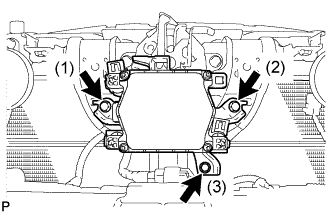
Tighten the 3 bolts on the millimeter wave radar sensor assembly.
- Torque:
- 5.5 N*m { 56 kgf*cm, 49 in.*lbf }
Tech Tips
Tighten the bolts in the order indicated in the illustration.
-
Connect the connector.
-
-
INSTALL FRONT BUMPER ASSEMBLY
-
ADJUST MILLIMETER WAVE RADAR SENSOR ASSEMBLY (w/ Dynamic Radar Cruise Control System)
-
INSPECT HOOD SUB-ASSEMBLY
-
Check that the clearance measurements of areas *a through *e are within each standard range.
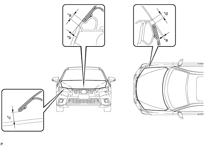
Standard Clearance Area Measurement Area Measurement *a 3.3 to 7.3 mm (0.130 to 0.287 in.) *b -1.5 to 1.5 mm (-0.0591 to 0.0591 in.) *c 5.65 to 9.65 mm (0.222 to 0.380 in.) *d 2.5 to 5.5 mm (0.0984 to 0.217 in.) *e -0.6 to 2.4 mm (-0.0236 to 0.0945 in.) - -
-
-
ADJUST HOOD SUB-ASSEMBLY