WINDSHIELD GLASS REMOVAL
-
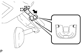
REMOVE FRONT WIPER ARM HEAD CAP
-
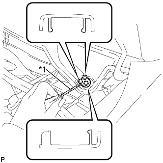
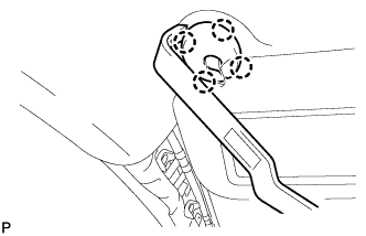
Text in Illustration *1 Protective Tape Using a screwdriver, disengage the 3 claws and remove the front wiper arm head cap.
Tech Tips
-
Tape the screwdriver tip before use.
-
Use the same procedure for the RH side and LH side.
-
-
-
REMOVE FRONT WIPER ARM AND BLADE ASSEMBLY LH
-
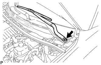
Remove the nut and the front wiper arm and blade assembly LH.
-
-
REMOVE FRONT WIPER ARM AND BLADE ASSEMBLY RH
-
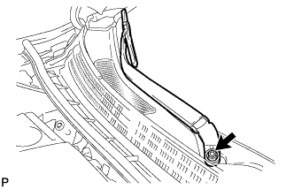
Remove the nut and the front wiper arm and blade assembly RH.
-
-
REMOVE FRONT NO. 2 SIDE PANEL PROTECTOR LH
-
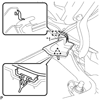
Text in Illustration *1 Double-sided Tape Disengage the clip and guide, and remove the front No. 2 side panel protector LH.
-
-
REMOVE FRONT NO. 2 SIDE PANEL PROTECTOR RH
Tech Tips
Use the same procedure as for the LH side.
-
REMOVE COWL TOP VENTILATOR LOUVER SUB-ASSEMBLY
-
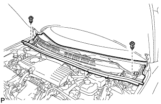
Remove the 2 clips.
-
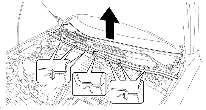
Disengage the 6 claws and guide as shown in the illustration.
-
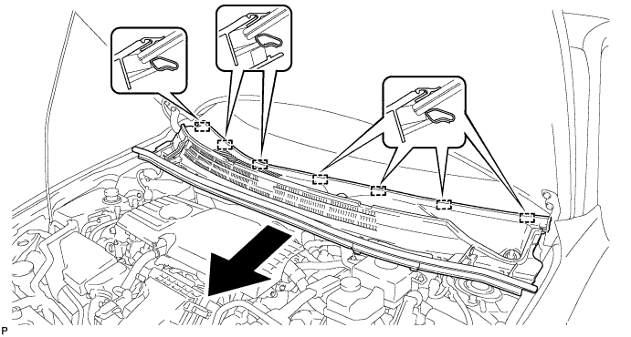
Disengage the 7 guides and pull out the cowl top ventilator louver sub-assembly as shown in the illustration.
-
-
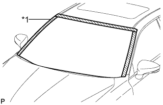
REMOVE WINDSHIELD OUTSIDE MOULDING LH
-
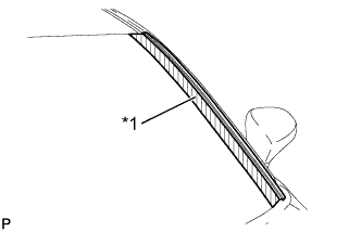
Text in Illustration *1 Protective Tape Put protective tape around the windshield outside moulding.
-
Using a moulding remover, disengage the 10 claws.
-
Disengage the guide and remove the windshield outside moulding.
-
-
REMOVE WINDSHIELD OUTSIDE MOULDING RH
Tech Tips
Use the same procedure as for the LH side.
-
REMOVE INNER REAR VIEW MIRROR STAY HOLDER COVER (w/ EC Mirror)
-
w/o Rear View Monitor System:
-
Disengage the 2 guides and slide the inner rear view mirror stay holder cover as shown in the illustration.
-
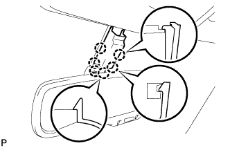
Disengage the 6 claws and remove the inner rear view mirror stay holder cover.
-
-
w/ Rear View Monitor System:
-
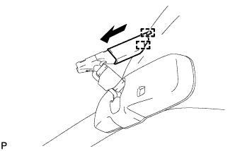
Disengage the 2 guides and slide the inner rear view mirror stay holder cover as shown in the illustration.
-
Disengage the 2 claws and remove the inner rear view mirror stay holder cover.
-
-
-
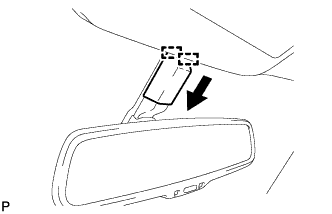
REMOVE INNER REAR VIEW MIRROR ASSEMBLY (w/o EC Mirror)
-
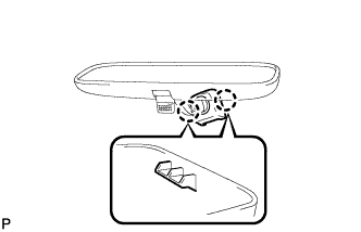
Disengage the 2 claws and disconnect the inner mirror base cover.
-
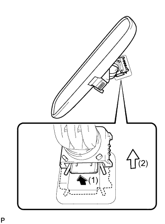
Pull the lever in the direction indicated by the arrow in the illustration, and slide the inner rear view mirror assembly upward to remove it.
-
-
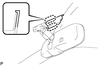
REMOVE INNER REAR VIEW MIRROR ASSEMBLY (w/ EC Mirror)
-
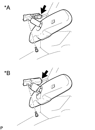
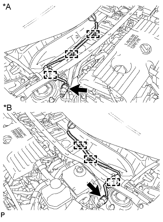
Text in Illustration *A w/o Rear View Monitor System *B w/ Rear View Monitor System Disconnect the connector.
-
Using a T20 "TORX" socket wrench, remove the screw and inner rear view mirror assembly.
-
-
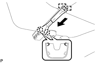
REMOVE RAIN SENSOR COVER (w/ Rain Sensor)
-
Disengage the 2 guides and disconnect the rain sensor cover as shown in the illustration.
-
Disengage the 2 claws and remove the rain sensor cover.
-
-
REMOVE RAIN SENSOR (w/ Rain Sensor)
-
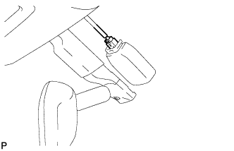
Disconnect the connector.
-
Text in Illustration *1 Stopper Release the stopper by pulling the stopper down and disconnect the rain sensor as shown in the illustration.
-
-
REMOVE PROTECTOR (w/ Humidity Sensor)
-
Disengage the 2 guides and slide the protector as shown in the illustration.
-
Disengage the 2 claws and remove the protector.
-
-
REMOVE HUMIDITY SENSOR (w/ Humidity Sensor)
-
Disconnect the connector.
-
Text in Illustration *1 Stopper Release the stopper by pulling it down.
-
Remove the humidity sensor as shown in the illustration.
-
-
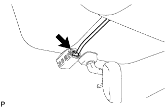
DISCONNECT FRONT DOOR OPENING TRIM WEATHERSTRIP LH
-
Disconnect the front door opening trim weatherstrip.
-
Remove the residual weatherstrip sealant from the body of the vehicle using cleaner.
Note
Remove the sealant completely. Any residual sealant may transfer to other areas of the vehicle when removing/installing the interior parts.
-
-
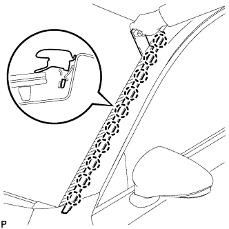
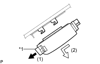
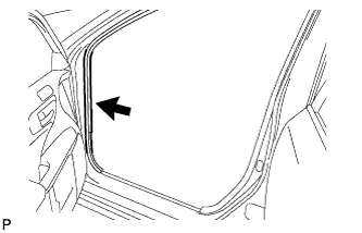
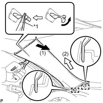
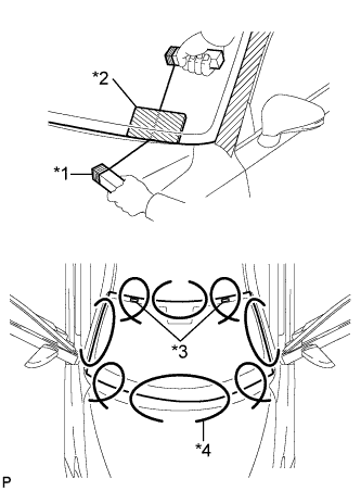
REMOVE FRONT PILLAR GARNISH LH
-
Text in Illustration *1 Front Pillar Garnish Clip Pull the upper part of the garnish toward the inside of the cabin and disengage the 2 clips.
Tech Tips
Make the front pillar garnish LH hang down from the front pillar garnish clip.
-
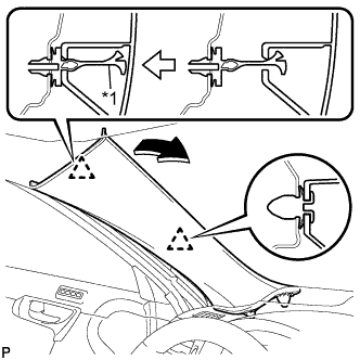
Text in Illustration *1 Protective Tape Turn the end of the front pillar garnish clip 90° with needle-nosed pliers and remove it from the front pillar garnish LH.
Note
-
Front pillar garnish clips are reusable if they are not removed from the vehicle and have no damage.
-
Replace the front pillar garnish clips with new ones if they are removed from the vehicle.
Tech Tips
Tape the tips of the needle-nosed pliers before use.
-
-
Disengage the 2 guides.
-
w/o Front Center Speaker:
-
Remove the front pillar garnish LH by pulling it in the direction indicated by the arrow (2) in the illustration.
-
-
w/ Front Center Speaker:
-
Disconnect the front pillar garnish LH by pulling it in the direction indicated by the arrow (2) in the illustration.
-
Disconnect the connector and remove the front pillar garnish LH.
-
-
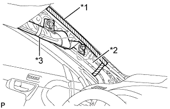
Text in Illustration *1 Adhesive Tape *2 Protective Cover *3 Curtain Shield Airbag Assembly Protect the curtain shield airbag assembly.
-
Cover the airbag with a cloth or piece of nylon and secure the ends of the cover with tape as shown in the illustration.
Note
Cover the curtain shield airbag with a protective cover as soon as the front pillar garnish is removed.
-
-
-
DISCONNECT FRONT DOOR OPENING TRIM WEATHERSTRIP RH
Tech Tips
Use the same procedure as for the LH side.
-
REMOVE FRONT PILLAR GARNISH RH
Tech Tips
Use the same procedure as for the LH side.
-
REMOVE MAP LIGHT ASSEMBLY
-
Open the overhead console.
-
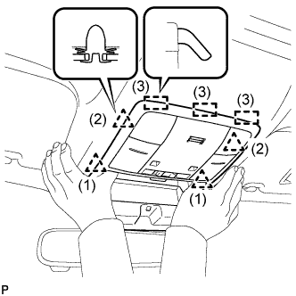
Disengage the 4 clips and 3 guides as shown in the illustration.
-
Disconnect the connector and remove the map light assembly.
-
-
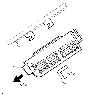
REMOVE NO. 1 ROOM LIGHT ASSEMBLY
-
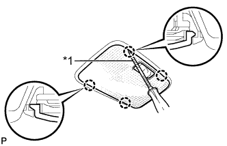
Text in Illustration *1 Protective Tape Using a screwdriver with its tip wrapped with protective tape, disengage the 4 claws and remove the No. 1 room light lens.
-
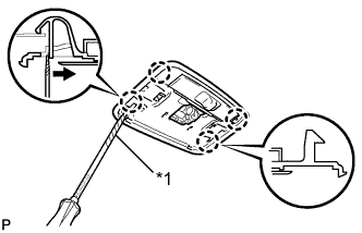
Text in Illustration *1 Protective Tape Using a screwdriver with its tip wrapped with protective tape, disengage the 4 claws and disconnect the No. 1 room light housing as shown in the illustration.
-
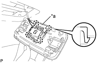
Text in Illustration *a Room Light Switch Base Disengage the 4 claws and disconnect the room light switch base from the No. 1 room light housing.
-
-
REMOVE ASSIST GRIP SUB-ASSEMBLY
-
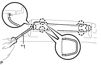
Text in Illustration *1 Protective Tape Using a screwdriver, disengage the 6 claws and remove the 2 assist grip covers.
Note
Do not forcibly pry the assist grip covers to prevent them from being deformed.
Tech Tips
Tape the screwdriver tip before use.
-
Disengage the 2 clips and remove the assist grip sub-assembly.
-
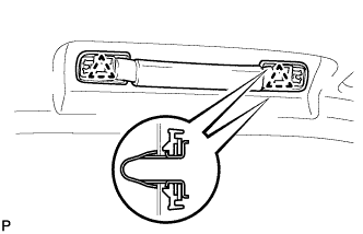
Remove the 2 clips from the vehicle body.
Tech Tips
Use the same procedure for the other 3 assist grip sub-assemblies.
-
-
REMOVE VISOR BRACKET COVER (for LH Side)
-
Using a moulding remover, disengage the 4 claws and remove the visor bracket cover LH.
-
-
REMOVE VISOR ASSEMBLY LH
-
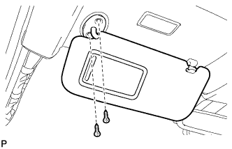
Remove the 2 screws and the visor assembly LH.
-
-
REMOVE VISOR BRACKET COVER (for RH Side)
Tech Tips
Use the same procedure as for the LH side.
-
REMOVE VISOR ASSEMBLY RH
Tech Tips
Use the same procedure as for the LH side.
-
REMOVE VISOR HOLDER
-
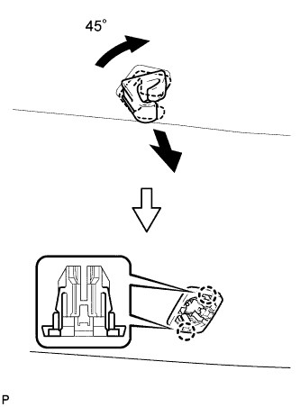
Turn the visor holder approximately 45° and pull it out as shown in the illustration.
-
Disengage the 2 claws and remove the visor holder.
Tech Tips
Use the same procedure for the other visor holder.
-
-
REMOVE SLIDING ROOF OPENING TRIM MOULDING (w/ Sliding Roof)
-
Remove the sliding roof opening trim moulding.
-
-
REMOVE ROOF HEADLINING ASSEMBLY
-
Slightly lower the front section of the roof headlining assembly so that the windshield glass can be removed.
Tech Tips
It is not necessary to completely remove the roof headlining assembly.
-
-
REMOVE WINDSHIELD GLASS SUB-ASSEMBLY
-
w/ Front Window Deicer System:
-
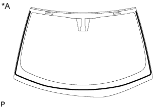
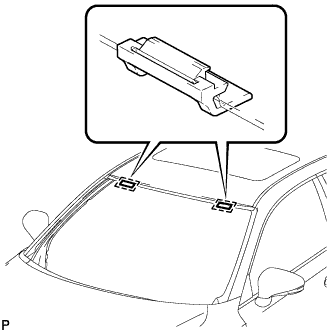
Text in Illustration *A LHD *B RHD Disengage the 3 clamps.
-
Disconnect the connector.
-
-
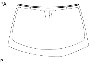
Text in Illustration *1 Protective Tape Apply protective tape to the area around the installation position of the windshield glass on the vehicle body to prevent it from being scratched.
-
Text in Illustration *1 Wooden Block *2 Plastic Sheet *3 Stopper *4 Piano Wire Pass a piano wire between the vehicle body and glass from the interior, as shown in the illustration.
-
Tie both wire ends to wooden blocks or similar objects that can serve as handles.
-
Cut off the adhesive by pulling the piano wire around the windshield glass sub-assembly.
Note
-
When separating the windshield glass sub-assembly, be careful not to damage the paint or interior and exterior ornaments.
-
To prevent the safety pad from being scratched when removing the windshield glass, place a plastic sheet between the piano wire and safety pad.
-
-
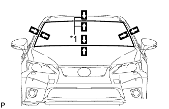
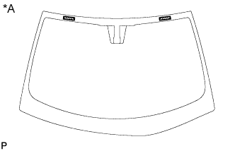
Text in Illustration *1 Matchmark Place matchmarks on the windshield glass sub-assembly and vehicle body on the locations indicated in the illustration.
Tech Tips
Matchmarks are not necessary if the windshield glass sub-assembly is not going to be reused.
-
Disconnect the windshield glass stoppers.
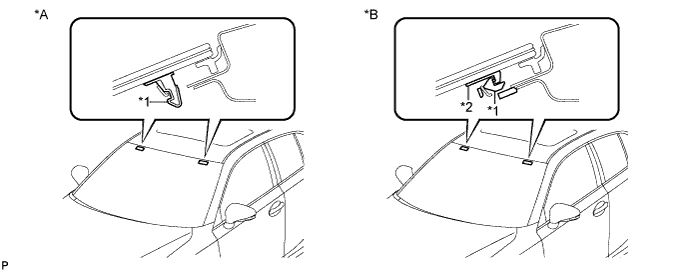
Text in Illustration *A 1-piece Type *B 2-pieceType *1 No. 1 Stopper *2 No. 2 Stopper Note
-
There are No. 1 and No. 2 stoppers on the windshield glass as shown in the illustration. Be careful not to damage the windshield glass when cutting off the adhesive.
-
To prevent the windshield glass from falling when performing this operation, be sure to hold the windshield glass using suction cups.
Tech Tips
Depending on the vehicle, either 1-piece or 2-piece type stoppers may be present.
-
-
Using suction cups, remove the windshield glass sub-assembly.
Note
-
Be careful not to drop the windshield glass sub-assembly.
-
Leave as much adhesive on the vehicle body as possible when removing the windshield glass sub-assembly.
-
-
-
REMOVE WINDSHIELD GLASS ADHESIVE DAM
-
When reusing the windshield glass sub-assembly:
-
Text in Illustration *A Back Side Using a scraper, remove the windshield glass adhesive dam.
Note
-
Be careful not to damage the windshield glass.
-
Be sure to replace the window glass adhesive dam with a new one.
-
-
-
-
REMOVE WINDSHIELD OUTSIDE MOULDING
-
When reusing the windshield glass sub-assembly:
-
Text in Illustration *A Back Side Using a scraper, remove the windshield outside moulding.
Note
-
Be careful not to damage the windshield glass.
-
Be sure to replace the windshield outside moulding with a new one.
-
-
-
-
REMOVE NO. 1 WINDSHIELD GLASS STOPPER (for 1-piece Type)
-
When reusing the windshield glass sub-assembly:
-
Text in Illustration *A Back Side Using a scraper, remove the 2 No. 1 windshield glass stoppers.
Note
-
Be careful not to damage the windshield glass.
-
Be sure to replace the 1-piece type No. 1 windshield glass stoppers with a new pair of 2-piece type No. 1 and No. 2 windshield glass stoppers.
-
-
-
-
REMOVE NO. 2 WINDSHIELD GLASS STOPPER (for 2-piece Type)
-
When reusing the windshield glass sub-assembly:
-

Text in Illustration *A Back Side Using a scraper, remove the 2 No. 2 windshield glass stoppers.
Note
-
Be careful not to damage the windshield glass.
-
Be sure to replace the No. 2 windshield glass stoppers with new ones.
-
-
-
-
REMOVE NO. 1 WINDSHIELD GLASS STOPPER (for 2-piece Type)
-
Remove the 2 No. 1 windshield glass stoppers.
Note
Be sure to replace the No. 1 windshield glass stoppers with new ones.
-
-
CLEAN WINDSHIELD GLASS
-
When reusing the windshield glass:
-
Using a scraper, remove any adhesive tape and adhesive residue from the windshield glass.
Note
Be careful not to damage the windshield glass.
-
Clean the outer circumference of the windshield glass with a non-residue solvent.
Note
-
Do not touch the windshield glass surface after cleaning it.
-
Even if using a new windshield glass, clean the windshield glass with a non-residue solvent.
-
-
-
-
CLEAN VEHICLE BODY
-
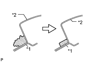
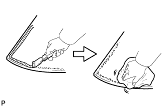
Text in Illustration *1 Adhesive *2 Body Clean and shape the contact surfaces of the vehicle body.
-
Using a knife, cut away excess adhesive on the contact surfaces of the vehicle body as shown in the illustration.
Note
Be careful not to damage the vehicle body.
Tech Tips
Leave as much adhesive on the vehicle body as possible.
-
Clean the contact surfaces of the vehicle body with a piece of cloth saturated with cleaner.
Tech Tips
Even if all the adhesive has been removed, clean the vehicle body.
-
-