- Click here
INSTALL NO. 2 ROOF SILENCER PAD (w/o Sliding Roof)
-
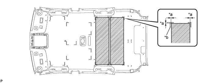
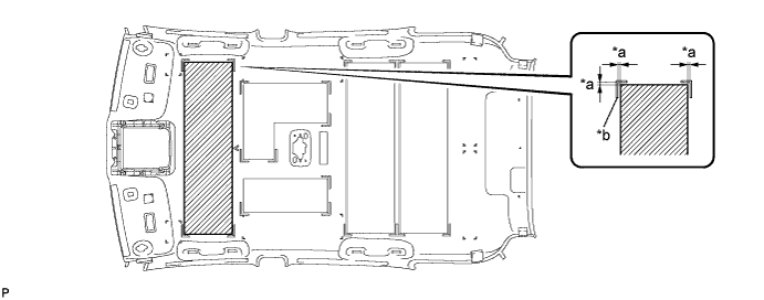
Align the markings on the roof headlining assembly with the 2 No. 2 roof silencer pads and install the pads using hot-melt glue as shown in the illustration.
Table 1. Text in Illustration *a 5 mm (0.197 in.) *b Marking
-
- Click here
INSTALL NO. 2 ROOF SILENCER PAD (w/ Sliding Roof)
-
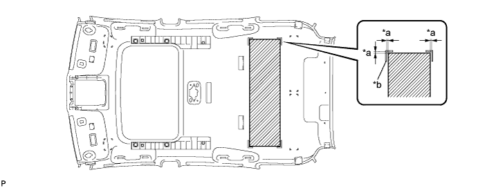
Align the markings on the roof headlining assembly with the No. 2 roof silencer pad and install the pad using hot-melt glue as shown in the illustration.
Table 2. Text in Illustration *a 5 mm (0.197 in.) *b Marking
-
- Click here
INSTALL NO. 4 ROOF SILENCER PAD (w/o Sliding Roof)
-
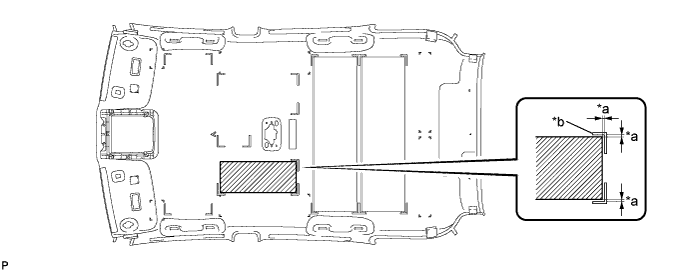
Align the markings on the roof headlining assembly with the No. 4 roof silencer pad and install the pad using hot-melt glue as shown in the illustration.
Table 3. Text in Illustration *a 5 mm (0.197 in.) *b Marking
-
- Click here
INSTALL NO. 3 ROOF SILENCER PAD (w/o Sliding Roof)
-
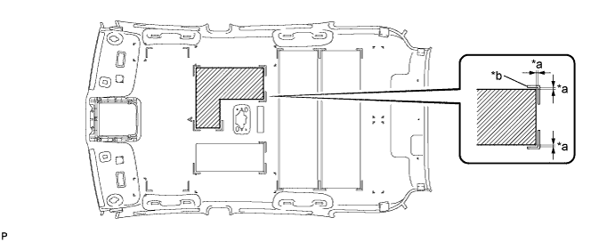
Align the markings on the roof headlining assembly with the No. 3 roof silencer pad and install the pad using hot-melt glue as shown in the illustration.
Table 4. Text in Illustration *a 5 mm (0.197 in.) *b Marking
-
- Click here
INSTALL NO. 1 ROOF SILENCER PAD (w/o Sliding Roof)
-
Align the markings on the roof headlining assembly with the No. 1 roof silencer pad and install the pad using hot-melt glue as shown in the illustration.
Table 5. Text in Illustration *a 5 mm (0.197 in.) *b Marking
-
- Click here
INSTALL NO. 1 ROOF WIRE
-
Apply double-sided tape as shown in the illustration.
-
Peel off the release paper from the double-sided tape.
-
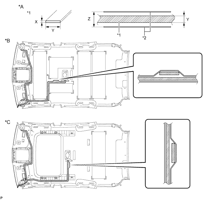
Attach the No. 1 roof wire along the double-sided tape so that the marking surface of the wire harness faces downward.
Table 6. Text in Illustration *A Tape Attachment Locations (Reference) *B w/o Sliding Roof *C w/ Sliding Roof - - *1 Double-sided Tape - - *a Marking - - Double-sided Tape Size X 1 mm (0.0394 in.) Y 15 mm (0.591 in.) Z 20 mm (0.787 in.) -
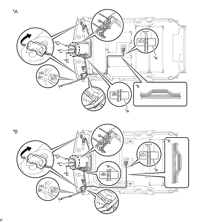
Align the pink marking tape (A) on the front part of the No. 1 roof wire with the front tab of the roof headlining assembly.
Table 7. Text in Illustration *A w/o Sliding Roof *B w/ Sliding Roof *C w/ EC Mirror *D w/ Rain Sensor (for LHD), w/ Humidity Sensor (for RHD) *E w/ Humidity Sensor (for LHD), w/ Rain Sensor (for RHD) - - *1 Joint Box - - *a Marking *b Adjustment Area -
Align the joint box with the roof headlining marking, and secure it using the tape.
-
Align the pink marking tape (B) on the No. 1 roof wire with the markings on the roof headlining assembly.
-
Attach the No. 1 roof wire, starting from the front tab of the roof headlining assembly to the pink marking tape (B) while aligning it with the double-sided tape.
Note:
-
Securely attach the No. 1 roof wire.
-
If any of the No. 1 roof wire is left loose, this will cause abnormal noise. Make sure to attach the No. 1 roof wire without leaving any loose.
-
-
Engage each clamp.
-
Attach the No. 1 roof wire, starting from the pink marking tape (B) to the visor connector RH part while aligning it with the double-sided tape.
Note:
-
Securely attach the No. 1 roof wire.
-
If any of the No. 1 roof wire is left loose, this will cause abnormal noise. Make sure to attach the No. 1 roof wire without leaving any loose.
-
-
Turn the visor connector RH clockwise approximately 90° to install the connector to the roof headlining assembly.
-
Turn the visor connector LH clockwise approximately 90° to install the connector to the roof headlining assembly.
-
Attach the No. 1 roof wire, starting from the joint box to the adjustment area while aligning it with the double-sided tape.
Note:
-
Securely attach the No. 1 roof wire.
-
If any of the No. 1 roof wire is left loose, this will cause abnormal noise. Make sure to attach the No. 1 roof wire without leaving any loose.
-
-
Align the pink marking tape (C) on the No. 1 roof wire with the markings on the roof headlining assembly.
-
Attach the No. 1 roof wire, starting from the pink marking tape (C) to the adjustment area while aligning it with the double-sided tape.
Note:
-
Securely attach the No. 1 roof wire.
-
If any of the No. 1 roof wire is left loose, this will cause abnormal noise. Make sure to attach the No. 1 roof wire without leaving any loose.
Tip:Secure the extra length of the No. 1 roof wire in the adjustment area.
-
-
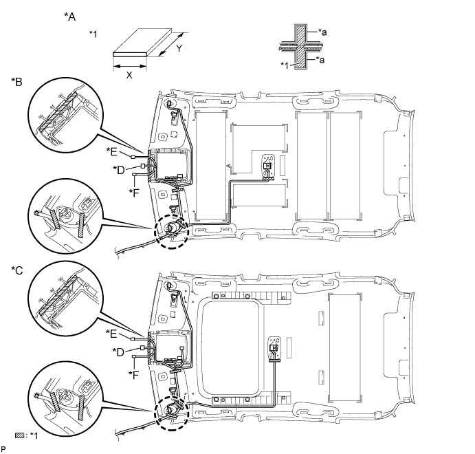
Apply adhesive tape by aligning it with the markings on the roof headlining.
Table 8. Text in Illustration *A Tape Attachment Locations (Reference) *B w/o Sliding Roof *C w/ Sliding Roof *D w/ EC Mirror *E w/ Rain Sensor (for LHD), w/ Humidity Sensor (for RHD) *F w/ Humidity Sensor (for LHD), w/ Rain Sensor (for RHD) *1 Adhesive Tape - - *a Marking - - Adhesive Tape Size X 20 mm (0.787 in.) Y 100 mm (3.94 in.)
-
- Click here
INSTALL NO. 2 ANTENNA CORD SUB-ASSEMBLY
Tip:The double-sided tape and tape are not available as supply parts. If these tapes still have enough adhesion to secure the roof headlining and antenna cord, reuse them. If the roof headlining has been replaced with a new one, or if the tape and/or the double-sided tape is no longer sticky, apply new tape following the procedure below.
-
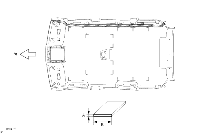
Apply new double-sided tape.
Table 9. Text in Illustration *1 Double-sided Tape - - *a Front Side - -
-
Remove the old double-sided tape from the roof headlining assembly.
-
Prepare the appropriate amount of new double-sided tape.
Tip:Be careful not to touch the adhesive surface.
Area Dimension A 1.0 mm (0.0394 in.) B 15.0 mm (0.591 in.) -
Apply the double-sided tape to the roof headlining while aligning the tape with the markings on the roof headlining assembly.
-
Peel off the release paper from the double-sided tape.
-
-
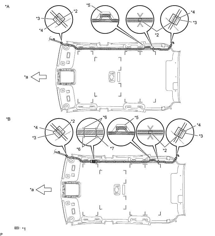
Install the No. 2 antenna cord sub-assembly to the roof headlining assembly from the front of the vehicle.
Table 10. Text in Illustration *A w/o G-BOOK System *B w/ G-BOOK System *1 Double-sided Tape *2 Marking Tape *3 Tape *4 Protrusion *5 Adjustment Area *6 Marking *7 Antenna Protector - - *a Front Side - - Tip:Align the taped part of the antenna cable with the protrusion of the roof headlining, and apply tape to secure the cable to the headlining.
-
w/o G-BOOK System:
-
Put the strips of the tape back to the positions shown in the illustration in order to secure the antenna cord to the roof headlining assembly.
Tip:
-
If the tape is no longer sticky, use other tape, such as packing tape, that has enough adhesion to secure the antenna cord to the roof headlining assembly.
-
For the right front corner of the roof headlining assembly, align the marking tape on the antenna cord with the protrusion of the roof headlining, and wrap tape around the antenna cord and roof headlining assembly once or twice to securely hold them.
-
For the right rear corner of the roof headlining assembly, align the marking tape on the antenna cord with the rear edge of the roof headlining, and secure the antenna cord to the roof headlining assembly with tape.
-
If the entire length of the antenna cord does not fit, adjust the length by tucking in the cord at the area shown in the illustration.
-
-
-
w/ G-BOOK System:
-
Put the strips of the tape back to the positions shown in the illustration in order to secure the antenna cord to the roof headlining assembly.
Tip:
-
If the tape is no longer sticky, use other tape, such as packing tape, that has enough adhesion to secure the antenna cord to the roof headlining assembly.
-
For the right front corner of the roof headlining assembly, align the marking tape on the antenna cord with the protrusion of the roof headlining, and wrap tape around the antenna cord and roof headlining assembly once or twice to securely hold them.
-
Align the markings on the roof headlining assembly with the antenna protector.
-
For the right rear corner of the roof headlining assembly, align the marking tape on the antenna cord with the rear edge of the roof headlining, and secure the antenna cord to the roof headlining assembly with tape.
-
If the entire length of the antenna cord does not fit, adjust the length by tucking in the cord at the area shown in the illustration.
-
-
-
- Click here
INSTALL VANITY LIGHT ASSEMBLY
-
Install the vanity light assembly (Click here).
Tip:Use the same procedure for the other vanity light.
-