LOWER INSTRUMENT PANEL INSTALLATION
-
INSTALL LOWER INSTRUMENT PANEL SUB-ASSEMBLY (w/o Instrument Cluster Finish Panel)
-
When using a new lower instrument panel sub-assembly:
-
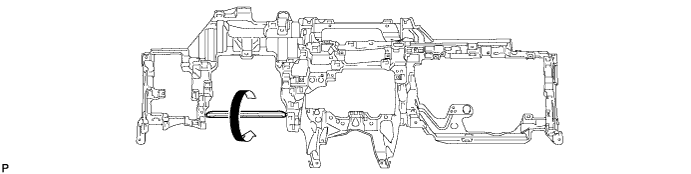
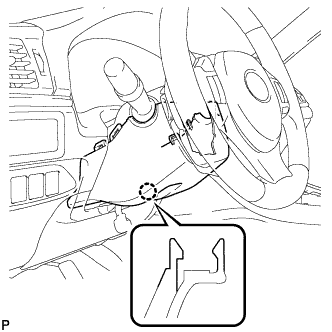
Immediately before installing the lower instrument panel sub-assembly, twist and cut off the portion shown in the illustration.
-
-
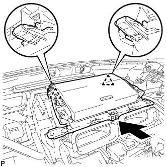
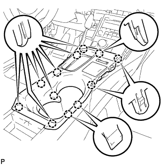
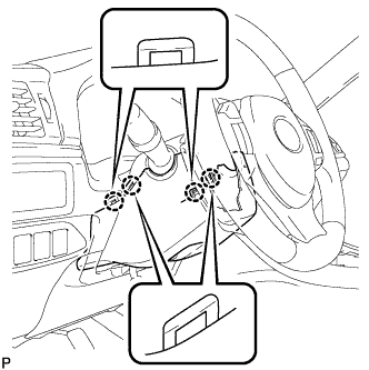
Engage the 2 guides.
-
Install the lower instrument panel sub-assembly with the 4 bolts <A>, 10 screws <B> or <C> and screw <D>.
-
Engage the 2 claws to connect the DLC3 connector.
-
for LHD:
-
Engage the claw to connect the protector.
-
-
Engage each clamp.
-
-
INSTALL LOWER INSTRUMENT PANEL SUB-ASSEMBLY (w/ Instrument Cluster Finish Panel)
-
When using a new lower instrument panel sub-assembly:
-
Immediately before installing the lower instrument panel sub-assembly, twist and cut off the portion shown in the illustration.
-
-
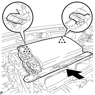
Engage the 2 guides.
-
Install the lower instrument panel sub-assembly with the 2 bolts <A>, 10 screws <B> or <C> and screw <D>.
-
Engage the 2 claws to connect the DLC3 connector.
-
for LHD:
-
Engage the claw to connect the protector.
-
-
Engage each clamp.
-
-
CONNECT HOOD LOCK CONTROL LEVER SUB-ASSEMBLY
-
Engage the 2 guides and claw to connect the hood lock control lever sub-assembly.
-
-
INSTALL INSTRUMENT PANEL BOX ASSEMBLY (w/ Instrument Panel Box)
-
Engage the 2 clips as shown in the illustration.
-
Install the instrument panel box assembly with the 2 bolts <A>.
-
Connect the connector.
-
-
INSTALL CENTER INSTRUMENT CLUSTER FINISH PANEL ASSEMBLY (w/ Navigation System)
-
Connect each connector.
-
Engage the clamp.
-
Engage the 2 clips as shown in the illustration.
-
Install the center instrument cluster finish panel assembly with the 2 bolts <A>.
-
-
INSTALL MAYDAY BATTERY WITH BRACKET (w/ G-BOOK System)
-
Install the mayday battery with bracket with the 2 bolts.
-
Connect the connector.
-
-
INSTALL NO. 1 CONSOLE BOX MOUNTING BRACKET
-
Engage the 2 guides.
-
Install the No. 1 console box mounting bracket with the 2 bolts <A>.
-
Engage each clamp.
-
-
INSTALL NO. 3 CONSOLE BOX MOUNTING BRACKET
-
Engage the 3 guides.
-
Install the No. 3 console box mounting bracket with the 4 bolts <A>.
-
Engage the clamp.
-
-
INSTALL TRANSMISSION INSTRUMENT PANEL SHIFT ASSEMBLY
-
Connect the 2 connectors to transmission instrument panel shift assembly.
-
Install the transmission instrument panel shift assembly with the 3 nuts.
- Torque:
- 12 N*m { 122 kgf*cm, 9 ft.*lbf }
-
-
INSTALL CONSOLE BOX RH
-
Engage the guide and 2 claws.
-
Engage the 3 clips.
-
Install the console box RH with the bolt <A> and clip.
-
-
INSTALL FRONT NO. 2 CONSOLE BOX INSERT
-
Engage the 5 claws to install the front No. 2 console box insert.
-
-
INSTALL CONSOLE BOX LH
-
Engage the guide and 2 claws.
-
Engage the 3 clips.
-
Install the console box LH with the bolt <A> and clip.
-
-
INSTALL CONSOLE BOX INSERT
-
Engage the 2 claws and 2 clips to install the console box insert.
-
-
INSTALL RADIO TUNER OPENING COVER WITH BRACKET (w/o Radio Receiver)
-
Connect each connector.
-
Install the radio tuner opening cover with bracket with the 4 bolts <A>.
-
-
INSTALL RADIO RECEIVER ASSEMBLY WITH BRACKET (for Radio Receiver Type)
-
Connect each connector.
-
Install the radio receiver assembly with bracket with the 4 bolts.
-
-
INSTALL MULTI-MEDIA MODULE RECEIVER ASSEMBLY WITH BRACKET (for Multi-Media Module Receiver Type)
-
Connect each connector.
-
Install the multi-media module receiver assembly with bracket with the 4 bolts.
-
-
INSTALL INTEGRATION CONTROL AND PANEL ASSEMBLY
-
Connect each connector.
-
Engage the clamp.
-
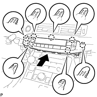
Engage the 2 guides and 6 claws to install the integration control and panel assembly.
-
-
INSTALL SHIFT LEVER KNOB SUB-ASSEMBLY
-
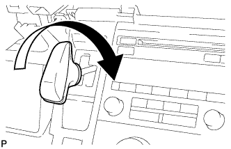
Turn the shift lever knob clockwise and install the shift lever knob sub-assembly.
-
-
INSTALL REAR CONSOLE BOX ASSEMBLY
-
Engage the 8 guides.
-
Install the rear console box assembly with the 4 bolts and 2 screws.
-
-
INSTALL CONSOLE BOX CARPET
-
Install the console box carpet.
-
-
INSTALL REAR CONSOLE BOX POCKET
-
Install the rear console box pocket.
-
-
INSTALL UPPER CONSOLE PANEL SUB-ASSEMBLY
-
Connect each connector.
-
Engage the clamp.
-
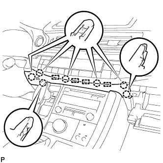
Engage the 12 claws to install the upper console panel sub-assembly.
Note
When installing the upper console panel sub-assembly, make sure not to pinch the wire harness connected to the front end of the remote touch (w/ Navigation System).
-
Close the console compartment door.
-
-
INSTALL UPPER NO. 1 CONSOLE PANEL GARNISH
-
Engage the 3 guides, clip and 4 claws to install the upper No. 1 console panel garnish.
-
-
INSTALL UPPER NO. 2 CONSOLE PANEL GARNISH
-
Engage the 2 guides, clip and 5 claws to install the upper No. 2 console panel garnish.
-
-
INSTALL AIR CONDITIONING CONTROL ASSEMBLY
-
Connect the connector.
-
Engage the 7 claws to install the air conditioning control assembly.
-
-
INSTALL LOWER CENTER INSTRUMENT PANEL FINISH PANEL
-
Engage the 4 guides and 7 claws to install the lower center instrument panel finish panel.
-
Close the glove compartment door.
-
-
INSTALL LOWER NO. 1 INSTRUMENT PANEL AIRBAG ASSEMBLY
-
Check that the power switch is off.
-
Check that the cable is disconnected from the negative (-) auxiliary battery terminal.
CAUTION:
Wait at least 90 seconds after disconnecting the cable from the negative (-) auxiliary battery terminal to disable the SRS system.
-
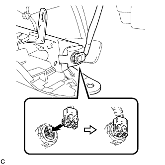
Connect the airbag connector to the lower No. 1 instrument panel airbag assembly.
Note
When connecting any airbag connector, take care not to damage the airbag wire harness.
-
Push in the lock to install the airbag connector.
-
Temporarily install the lower No. 1 instrument panel airbag assembly with the 6 claws and 3 guides.
-
Install the 4 bolts.
- Torque:
- 10 N*m { 102 kgf*cm, 7 ft.*lbf }
Note
Confirm that the lower No. 1 instrument panel airbag assembly is installed securely without any excessive gaps and is not protruding outward.
-
-
INSTALL NO. 1 INSTRUMENT PANEL UNDER COVER SUB-ASSEMBLY (for LHD)
-
Connect each connector.
-
Engage the clamp.
-
Engage the clip.
-
Install the No. 1 instrument panel under cover sub-assembly with the 2 screws <E>.
-
-
INSTALL NO. 1 INSTRUMENT PANEL UNDER COVER SUB-ASSEMBLY (for RHD)
-
Connect each connector.
-
Engage the clamp.
-
Engage the 2 clips.
-
Install the No. 1 instrument panel under cover sub-assembly with the screw <E>.
-
-
INSTALL STEERING COLUMN COVER
Note
If the lower steering column cover is installed in the incorrect order, it will not be possible to assemble the steering column cover.
-
Engage the 2 claws to install the upper steering column cover.
-
Engage the 4 clips and 2 guides to install the instrument panel cluster finish panel to the upper steering column cover.
-
Engage the 4 claws.
-
Engage the 2 claws.
Tech Tips
Press the area around the claws to engage them.
-
Turn the steering wheel assembly to the left to install the screw.
- Torque:
- 2.0 N*m { 20 kgf*cm, 18 in.*lbf }
-
Turn the steering wheel assembly to the right to install the screw.
- Torque:
- 2.0 N*m { 20 kgf*cm, 18 in.*lbf }
-
-
INSTALL COWL SIDE TRIM SUB-ASSEMBLY LH
-
Engage the claw and clip.
Note
-
Be sure to engage the clip securely.
-
If there is any damage, replace the garnish clip with a new one.
-
-
Install the cowl side trim sub-assembly LH with the clip.
-
-
INSTALL FRONT DOOR SCUFF PLATE LH
-
Engage the 4 claws, 2 guides and 4 clips to install the front door scuff plate LH.
-
-
INSTALL UPPER INSTRUMENT PANEL ASSEMBLY
-
INSPECT SHIFT LEVER
-
Turn the power switch on (READY).
-
Check that all available shift positions can be selected by moving the shift lever.
Tech Tips
After the transmission instrument panel shift assembly is replaced with a new one, perform the above operation. If this operation is not performed, moving the shift lever may not initially select shift positions.
-