POWER OUTLET SOCKET INSTALLATION
-
INSTALL NO. 2 POWER OUTLET SOCKET COVER (for Front Side)
-
Engage the 2 claws to install the No. 2 power outlet socket cover.
-
-
INSTALL NO. 3 POWER OUTLET SOCKET ASSEMBLY (for Front Side)
-
As shown in the illustration, align the protrusion of the No. 3 power outlet socket assembly and the notch of the No. 2 power outlet socket cover.
-
Engage the 2 claws to install the No. 3 power outlet socket assembly to No. 2 power outlet socket cover.
-
-
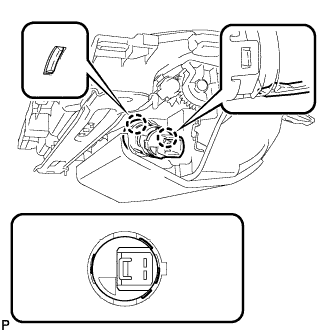
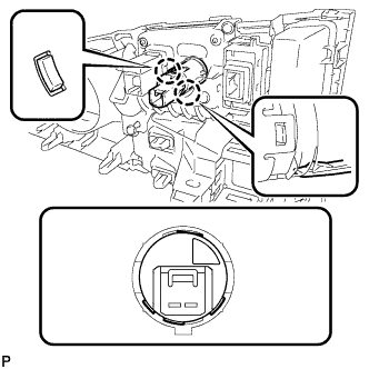
INSTALL INSTRUMENT PANEL BOX ASSEMBLY (for Front Side)
-
Connect the connector.
-
Engage the 2 clamps.
-
Engage the 2 clips as shown in the illustration.
-
Install the instrument panel box assembly with the 2 screws.
-
Engage the 4 guides and 3 claws, and install the instrument panel finish panel end.
-
Close the instrument panel box assembly door.
-
-
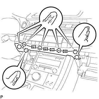
INSTALL INSTRUMENT CLUSTER FINISH PANEL SUB-ASSEMBLY (for Front Side)
-
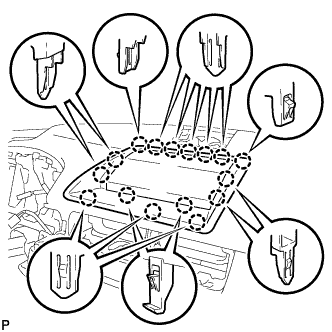
Engage the 16 claws to install the instrument cluster finish panel sub-assembly.
-
-
INSTALL CENTER INSTRUMENT PANEL REGISTER ASSEMBLY (for Front Side)
-
Connect the connector.
-
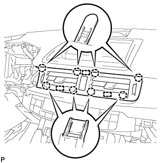
Engage the 3 guides and 8 claws to install the center instrument panel register assembly.
-
-
INSTALL NO. 2 POWER OUTLET SOCKET COVER (for Rear Side)
-
Engage the 2 claws to install the No. 2 power outlet socket cover.
-
-
INSTALL NO. 3 POWER OUTLET SOCKET ASSEMBLY (for Rear Side)
-
As shown in the illustration, align the protrusion of the No. 3 power outlet socket assembly and the notch of the No. 2 power outlet socket cover.
-
Engage the 2 claws to install the No. 3 power outlet socket assembly to No. 2 power outlet socket cover.
-
-
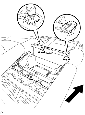
INSTALL UPPER CONSOLE PANEL SUB-ASSEMBLY (for Rear Side)
-
Connect each connector.
-
Engage the clamp.
-
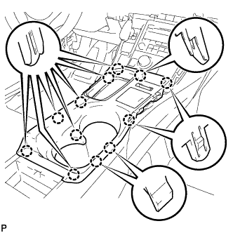
Engage the 12 claws to install the upper console panel sub-assembly.
Note
When installing the upper console panel sub-assembly, make sure not to pinch the wire harness connected to the front end of the remote touch (w/ Navigation System).
-
Close the console compartment door.
-
-
INSTALL UPPER NO. 1 CONSOLE PANEL GARNISH (for Rear Side)
-
Engage the 3 guides, clip and 4 claws to install the upper No. 1 console panel garnish.
-
-
INSTALL UPPER NO. 2 CONSOLE PANEL GARNISH (for Rear Side)
-
Engage the 2 guides, clip and 5 claws to install the upper No. 2 console panel garnish.
-
-
INSTALL LOWER CENTER INSTRUMENT PANEL FINISH PANEL (for Rear Side)
-
Engage the 4 guides and 7 claws to install the lower center instrument panel finish panel.
-
Close the glove compartment door.
-