AIR CONDITIONING SYSTEM Air Conditioning Control Panel Circuit
DESCRIPTION
-
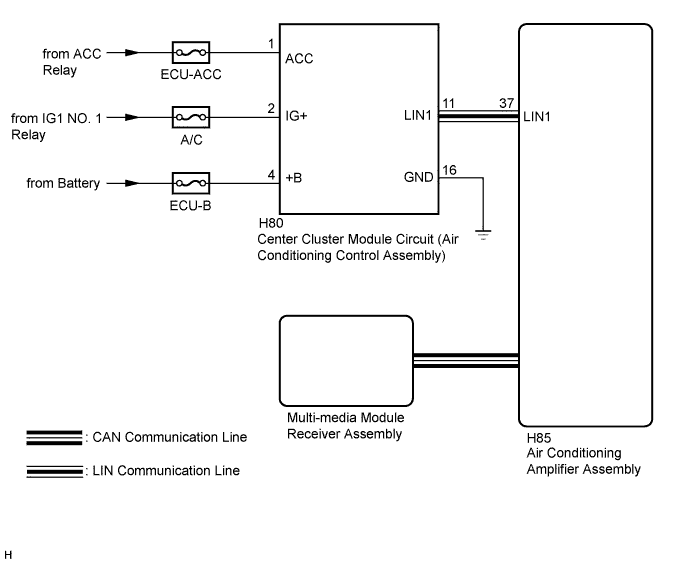
Center cluster module circuit (air conditioning control assembly) switch signals are sent to the air conditioning amplifier assembly via LIN communication.
The air conditioning amplifier assembly then sends these signals to the multi-media module receiver assembly via CAN communication.
w/ Navigation System:
-
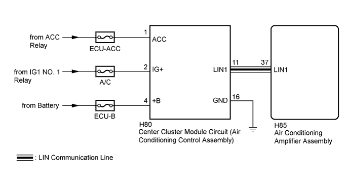
Center cluster module circuit (air conditioning control assembly) switch signals are sent to the air conditioning amplifier assembly via LIN communication.
w/o Navigation System:
WIRING DIAGRAM
-
w/ Navigation System
-
w/o Navigation System
INSPECTION PROCEDURE
Note
Inspect the fuses for circuits related to this system before performing the following inspection procedure.
PROCEDURE
-
CONFIRM MODEL
Result Result Proceed to w/o Navigation System A w/ Navigation System B
B 
CHECK NAVIGATION SYSTEM Click here
A 
-
CHECK HARNESS AND CONNECTOR (POWER SOURCE, GROUND)
-
Disconnect the center cluster module circuit (air conditioning control assembly) connector.
-
Measure the voltage according to the value(s) in the table below.
Standard Voltage Tester Connection Condition Specified Condition H80-1 (ACC) - Body ground Power switch off Below 1 V Power switch on (ACC) 11 to 14 V H80-2 (IG+) - Body ground Power switch off Below 1 V Power switch on (IG) 11 to 14 V H80-4 (+B) - Body ground Power switch off 11 to 14 V -
Measure the resistance according to the value(s) in the table below.
Standard Resistance Tester Connection Condition Specified Condition H80-16 (GND) - Body ground Always Below 1 Ω
NG 
REPAIR OR REPLACE HARNESS OR CONNECTOR
OK
-
-
CHECK HARNESS AND CONNECTOR (AIR CONDITIONING AMPLIFIER - CENTER CLUSTER MODULE CIRCUIT)
-
Measure the resistance according to the value(s) in the table below.
Standard Resistance Tester Connection Condition Specified Condition H80-11 (LIN1) - H85-37(LIN1) Always Below 1 Ω H80-11 (LIN1) - Body ground Always 10 kΩ or higher
NG
REPAIR OR REPLACE HARNESS OR CONNECTOR
OK
-
-
REPLACE CENTER CLUSTER MODULE CIRCUIT (AIR CONDITIONING CONTROL PANEL ASSEMBLY)
-
Replace the center cluster module circuit (air conditioning control assembly) with a new or a known good one Click here.
OK The center cluster module circuit (air conditioning control assembly) operation returns to normal.
NG
PROCEED TO NEXT SUSPECTED AREA SHOWN IN PROBLEM SYMPTOMS TABLE Click here
OK 
END (CENTER CLUSTER MODULE CIRCUIT WAS DEFECTIVE)
-
-
CHECK NAVIGATION SYSTEM
-
Check that the navigation system operates normally.
OK The navigation system operates normally.
NG
GO TO NAVIGATION SYSTEM Click here
OK
-
-
CHECK HARNESS AND CONNECTOR (POWER SOURCE, GROUND)
-
Disconnect the center cluster module circuit (air conditioning control assembly) connector.
-
Measure the voltage according to the value(s) in the table below.
Standard Voltage Tester Connection Condition Specified Condition H80-1 (ACC) - Body ground Power switch off Below 1 V Power switch on (ACC) 11 to 14 V H80-2 (IG+) - Body ground Power switch off Below 1 V Power switch on (IG) 11 to 14 V H80-4 (+B) - Body ground Power switch off 11 to 14 V -
Measure the resistance according to the value(s) in the table below.
Standard Resistance Tester Connection Condition Specified Condition H80-16 (GND) - Body ground Always Below 1 Ω
NG
REPAIR OR REPLACE HARNESS OR CONNECTOR
OK
-
-
CHECK HARNESS AND CONNECTOR (AIR CONDITIONING AMPLIFIER - CENTER CLUSTER MODULE CIRCUIT)
-
Measure the resistance according to the value(s) in the table below.
Standard Resistance Tester Connection Condition Specified Condition H80-11 (LIN1) - H85-37(LIN1) Always Below 1 Ω H80-11 (LIN1) - Body ground Always 10 kΩ or higher
NG
REPAIR OR REPLACE HARNESS OR CONNECTOR
OK
-
-
REPLACE CENTER CLUSTER MODULE CIRCUIT (AIR CONDITIONING CONTROL ASSEMBLY)
-
Replace the center cluster module circuit (air conditioning control assembly) with a new or a known good one Click here.
OK The center cluster module circuit (air conditioning control assembly) operation returns to normal.
NG
PROCEED TO NEXT SUSPECTED AREA SHOWN IN PROBLEM SYMPTOMS TABLE Click here
OK
END (CENTER CLUSTER MODULE CIRCUIT WAS DEFECTIVE)
-